
Radio-controlled Gus class hovercraft
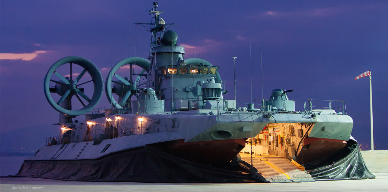
I'll tell you a story of love at first sight.
It all started with an ADSL connection: I was finally going to access all those hovercraft pictures, which until then I had only caught glimpses of, since they took too long to load. One of my first stops was the British Hovercraft Museum website. That's where I first saw the Zubr Class hovercraft. Building a model of it became a dream. The image above, on the left, was my computer wallpaper for a long time!
Making a working machine ? Not easy, but possible. Building the superstructures ? I didn't have the time or the skills.
And then Didier came to see me. With nothing more than the photo of the Zubr, he immediately recognized it as a Soviet/Russian machine and gave me a rough estimate of its construction date. He was enthusiastic about the idea of building a static model, but making a radio-controlled version — that would be a completely different challenge.

DESIGN – It's great to have a friend who's willing to design a Zubr. Didier will take care of the superstructures, but before that, we need to make a working machine. I have photos of the beast and a blueprint.
From there, a lot of thought is needed to understand the machine's design. I'll spare you the details of the research and calculations. The Zubr has four distinct air cushions, each one powered by a vertical turbine.
The front ramp and the rear door, when lowered, don't interfere with the skirt. The three rear turbines that drive the four-bladed propellers are faired and feature a bulb to improve efficiency. If we want to stay true to the scale model, we'll also need to calculate the motor power and make a realistic weight estimate.
There are two possible approaches:
– In a hull that looks like the Zubr, I build a classic lift system with a motor and a propeller,
– Or I stick faithfully to the original with four lift turbines.
I hesitated for a while between the simplicity of the first option and the technical elegance of the second. Discovering suitable turbines in the Graupner catalog ultimately pushed me toward the second choice.
(I do not own this image, all rights and credit to its owner – source here.)
From there, everything followed naturally. Given the diameter of a Zubr turbine compared to a Graupner turbine, I calculated the appropriate scale: 1/48. From that, I derived the required power: 70,000 horsepower divided by 48×48×48 = 466 watts for a length of 1.30 meters. The choice of motors followed accordingly: four Graupner Speed 400 7.2V motors for inflating the skirt, and three Graupner Speed 480 7.2V motors for thrust—same voltage across the board.
The propellers are four-bladed units from a hydrofoil model, the Fluppy, which will need to be trimmed down to the correct diameter. As for the controls: one channel per propulsion motor, one channel for lift, one for the doors, and one for steering—that makes six in total.
The blueprint was redrawn from photocopied enlargements of various online plans. And so, one day, my garage was overtaken by RC equipment and a large workbench.
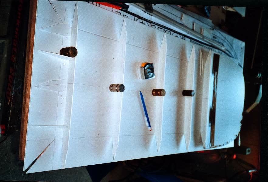
HULL – After thinking, action.
I preferred not to use resin, but to work with materials closer to those of the real machine. The real Zubr is made with aluminum-manganese "plywood." I chose to build the hull using two polypropylene sheets with a long central partition. A “box construction,” with frames and partitions on a lower hull.
The structure was made using polypropylene formers to better replicate the aluminum-manganese sandwich of the actual craft.
Everything was cut with a utility knife and assembled using sprayed hot glue.
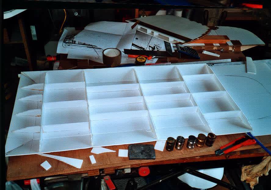
Hull partitioning, giving little weight and a lot of rigidity.
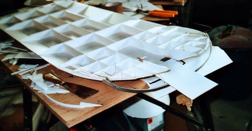
Front view: we can see the hinge, the ramp, and the front bulkhead.
The front is more problematic because it is not in the same plane as the rest of the machine, and it has to support the hinge. I built a more compact partition to increase rigidity, along with double partitions at the hinge pin.
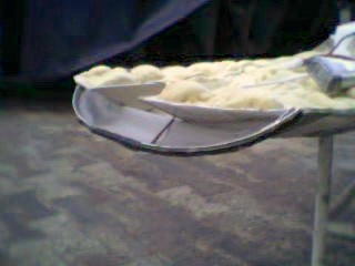
The hinge is sealed with a stretched canvas made from real skirt fabric.
You can also see the buoyancy foam that was added
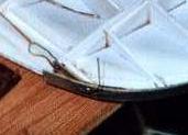
Apologies for the poor-quality picture — here, you can see the detail of the two arms at the axis level. This hinge is made from a single piece of flat aluminum. The central section is lower, achieved by folding the bar.
There's a double thickness underneath the ramp. The ends are reinforced with brackets riveted using POP rivets. The hinge pin is made from piano wire.
Last difficulty for this part: having a nice hinge is not enough — it also needs to be airtight. On the inside of the hinge bar and the underside of the hull, I glued a piece of flexible fabric that I usually use for the skirts of smaller models (gray K-Way fabric). I created the pattern of the part with paper to get a proper development... or nearly so. The K-Way fabric adheres very well to either SuperGlue or neoprene glue.
Advantage of SuperGlue: fewer marks. Advantage of neoprene: sticks to almost all surfaces.
At the end of the day, I have a skeleton ready to receive the lift turbines, the skirt, propulsion, and radio control.
LIFT SYSTEM
I had a nice, light, and rigid hull. I had to bring it to life.
The very centered position of the turbines relative to the skirt posed a problem of air distribution. To achieve lift, air must be directed into both the skirt (the area enclosed by the fabric) and the cushion (the space beneath the hovercraft that, through pressurization, lifts the vehicle). The airflow is approximately one-third toward the skirt and two-thirds toward the cushion. To feed the skirt properly, I had to offset the airflow outward, while being careful not to exceed the future outer bodywork.
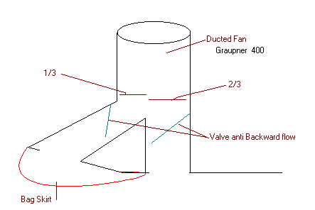
Lift section diagram - motor and EDF not drawn.
Wanting to stay as close as possible to the Zubr, I initially planned to create four separate cushions. Each turbine was supposed to supply one cushion. I designed four identical units by cutting part of each turbine duct and adding a deflector.
Unfortunately, I hadn't accounted for the fragility of the turbines' carbon fiber housings. You can't just cut part of the circumference without breaking the rest.
Originally, each turbine had a 12 cm duct, which was ideal. But once broken, it was reduced to only 6 cm. I had to "improvise" distribution boxes under each turbine. These boxes include a deflector—a slanted piece of partition to split and direct the airflow. I also added anti-backflow valves: pieces of skirt fabric that prevent air from flowing backward in case a turbine fails.
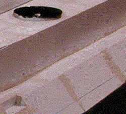
Lift turbine with its casing - Even if the finishes are not complete, the purpose of the air distributors' shape is already clear.
Each turbine is glued onto a plate that allows for mounting and fine-tuning the positioning and vertical alignment of the turbine.
Once the turbine is fixed in place, each lift well is reinforced with two lateral fabric strips to prevent any separation between the two parts, and with a fabric strip around the perimeter—with the idea of potentially adding an inspection hatch for adjustments during the skirt installation.
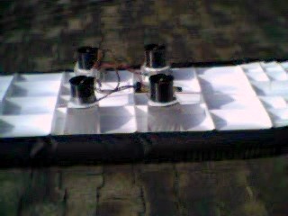
Side view - we see the closing fabrics under tension by the effect of pressure.
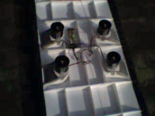
The four lift wells. First test run of the four motors together.
Electric wiring is very simple.
These four motors are designed to run together at full power. I grouped the wires in pairs on each side and added a switch that will be controlled by radio.
Tests without the skirt were satisfactory. One annoying detail: tightening the propeller cone was impossible on one of the four motors. The solution was a drop of Loctite. This makes disassembly impossible without drilling out the screw.
After several hours of use on different models, I've never had to replace a turbine. So it's not a major drawback.
THE SKIRT
A specialized component in its own right, the skirt is both very simple and very complex.
Very simple because it's just canvas inflated by a stream of air.
Very complex because a small mistake can cause the whole thing to fail.
The Zubr's skirt is of the bag-segmented type. This means that at the top there is a kind of “sausage” — the inflated part of the skirt, into which air flows from the turbines — and below that, a segmented skirt made up, as the name implies, of half-glove segments, so to speak.
Once this initial difficulty is understood, one must pay attention to the profile of the front part of the skirt, which differs from the rest, and also to the segments at the rear, which must not fill with water when stationary.
The half-glove fingers are fed with air from both the inflated skirt and the cushion underneath.
Final difficulty: there are internal partitions separating the four cushions. I started by making a model out of cardboard and plastic, to scale.
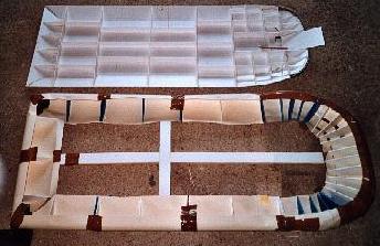
First try - the hull shape is above, and below is a draft of an inflated skirt
We can see from the shape that while the sides and rear are straightforward, the front requires much more attention due to its varying diameter. Each section of the shape was calculated based on data from blueprints found online.
I had some black skirt fabric in stock from my personal hovercraft builds. It was waterproof and fairly flexible, and it seemed suitable for this project. So I began working on the inflated skirt. This fabric can only be sewn, so each part was cut out, the shapes placed on the template, and then, once adjusted, they were stitched together.
Then came the task of cutting the two hundred and twenty segments that make up the bottom part of the skirt. Each one was sewn together as well.
I then cut out 220 segments again, which I glued and stitched onto an attachment strip at the base of the inflated skirt. That is, I glued the top edge of the center of each glove segment, and then using a wire threaded through the tapered part on each side, I attached both sides of the segment to the center of the inflated skirt.
Once that was done, I still had to make holes in the inflated skirt to supply air to each segment. By taking the total area feeding the inflated skirt and dividing it by 220, I got the area required for a segment's feed hole.
Not wanting to make holes that were too large, I chose to make three smaller ones per half-glove: a small one at the back, a medium one on the side, and a large one at the front.
Using a multi-head hole punch, I drilled 660 small holes — three per segment.
I glued the skirt in place and adjusted the turbine air outlets to optimize performance.
Because this skirt was less "snappy" than the previous one, there was too much leakage between segments. I added a drop of glue between each segment so they would stay well connected.
Final detail: I needed to make sure that the rear segments wouldn't scoop water while the hovercraft was moving.
I didn't want to make specialized segments, so I added a “bib” under the hull to block the half-glove fingers when pressed by water.
Made from the same skirt fabric, it has a trapezoidal shape and sticks to the underside of the craft.

The front of the skirt at rest - we see the gluing of the skirt on the front door. Again, this result gave me satisfaction : the skirt looked a lot like the big one and the doors could work without worries.
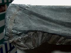
Back of the skirt - this is the right rear corner. We see the upper part which looks like a bag skirt and the lower part, containing "finger-type" segments.
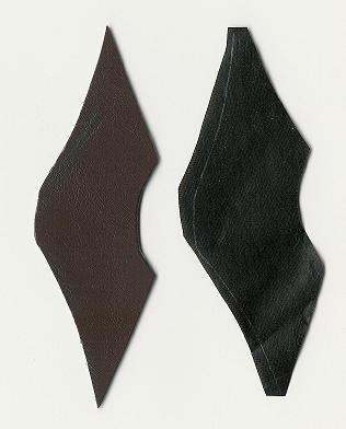
Template of a "finger segment". There are 220 under the skirt.
During the first tests, nothing worked. I had made holes to allow the skirt to refill the air cushion, but it wasn’t enough. I added a few more, which improved the lift slightly but didn’t solve the underlying problems.
The solution came from a former EDF (French electricity company) employee who had extensive knowledge of fans. According to him, using four fans to blow air into the same chamber created interference. There needed to be a balance between the four lift wells.
I resumed testing by running one, then two, then three motors. Everything worked well— the check valves functioned properly, and the machine lifted off. But as soon as I turned on the fourth motor, the same erratic behavior returned. I kept experimenting, adjusting the size of the outlets feeding the cushion and the dimensions of the deflectors, trying to find the right balance.
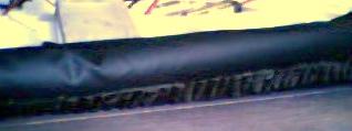
Side view - We can clearly see the fingers segments when the skirt is inflated.
Finally, it was flying. I grabbed a few water bottles to load down the Zubr. With all four motors running, the air cushion could lift 8 kg. When I shut them off, the skirt formed a black semicylinder all around the base. It looked promising—except that the front door wouldn’t lower completely: the skirt fabric was too elastic. I set that issue aside for later and focused instead on the central partitions.
That was a mistake. It forced me to make a lot of changes, only to undo them later. In the end, I gave up. In operation, you can’t tell the difference anyway.
When the model was stopped, though, the skirt’s appearance bothered me. It didn’t fall naturally to the ground like on the real Zubr. Worse, the doors required far too much power to overcome the skirt’s elasticity. I dismantled the skirt and started over from scratch, this time using the K-way fabric I had already used to seal the hinge.
Step one: dyeing the fabric changed its color from grey to dark brown-black.
Step two: since the fabric was sticky, I created a new mold using pipe insulation foam. K-way fabric bonds very well to itself with super glue. I fitted the skirt to the mold by gluing it into place. In some areas, I added small strips to reinforce corners or weak spots.
PROPULSION AND RADIO CONTROL
I thought I was in for a quick and easy job: install the propulsion motors, set up the radio control, and wire everything together. That meant: adding a speed controller to each Speed 480 motor, a switch for the lift system, and control cables for both steering and the doors.
While the beginning went smoothly, development turned out to be more complicated.
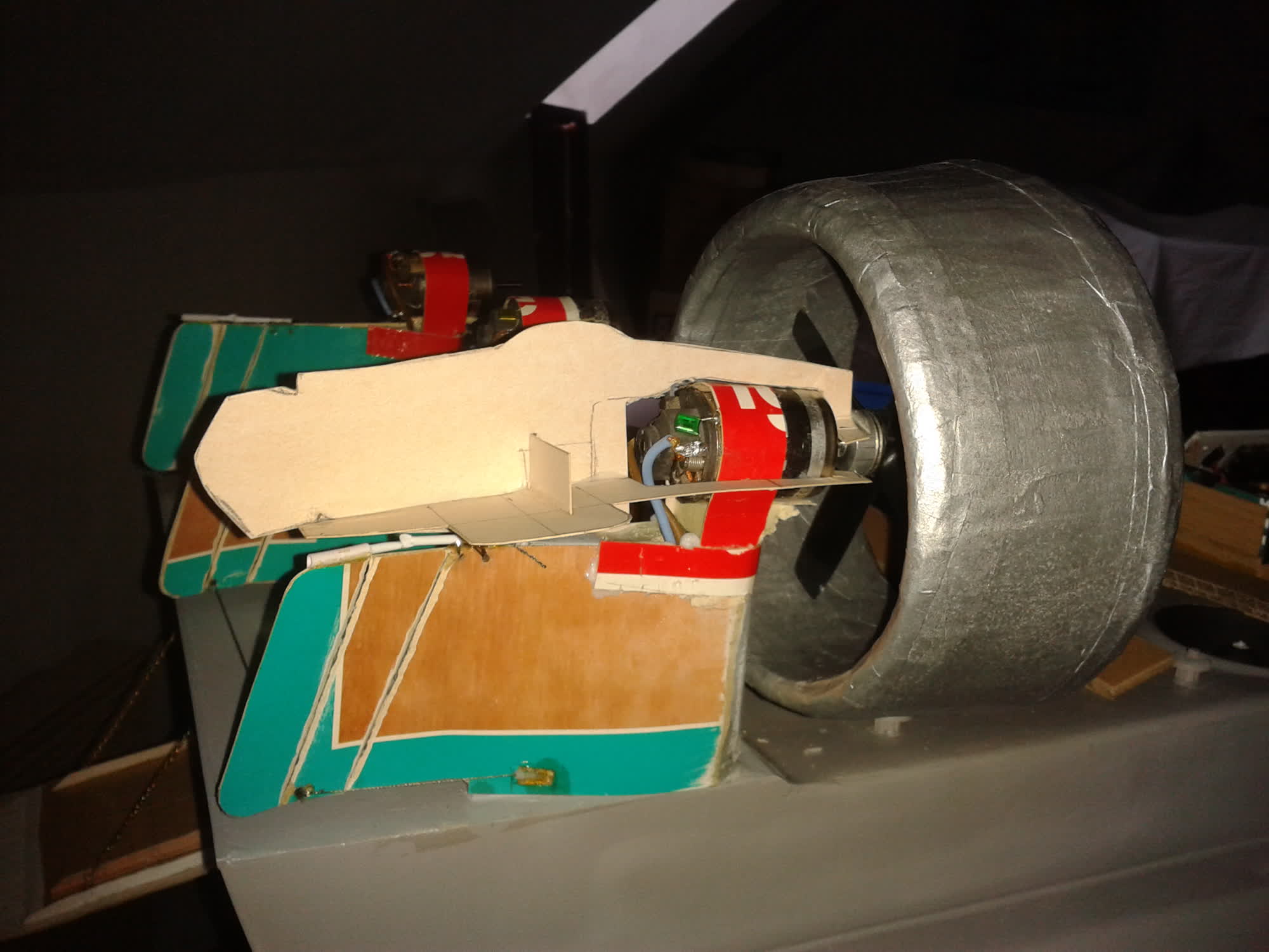
Each of the three Speed 480 motors is mounted on a fiberglass mast. To add rigidity, the three masts are connected together, and the thrust is absorbed by an angled strut braced against the hull. The original four-blade propellers were far too large for the Speed 480s and the size of the model. Once installed on the motors, I resized each propeller: running the motor at low speed, I trimmed the tips of the blades using sandpaper or a power file. Going slowly makes the process safe and precise.
To match the layout and diameters of the turbine housings, the propeller mount is installed with a series of washers to offset the propeller shaft as far as possible from the motor. For now, the motors are temporarily held in place with cable ties. The final mounts will need to account for the internal supports of the propeller shrouds.
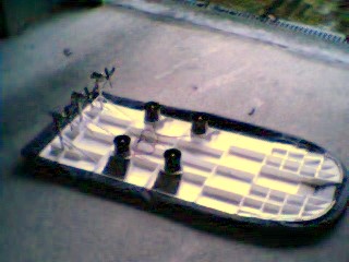
View of the seven motors : three Speed 480 and four speed 400, for a total power of 200 W.
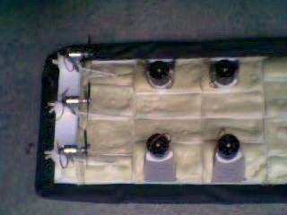
Top view - we can see the buoyancy foam.
Each cell was filled with two-component polyurethane foam and closed, for buoyancy and rigidity.
At this stage, each compartment of the hull is filled with two-component polyurethane foam to provide final structural rigidity and ensure buoyancy. This foam has the advantage of being water-resistant due to its closed-cell structure.
The radio control system is installed on a platform glued directly onto the foam, between the four lift turbines—beneath what will later become the Zubr’s island—with the intention of sealing this area off. At the rear, close to the propulsion motors, the three speed controllers are mounted vertically to ensure proper ventilation. Just in front of them, I install the power distribution.
The Zubr is designed to run on three 7.2-volt batteries: two for propulsion and one for lift. I connected the three motors and the two propulsion batteries in parallel. All switches are wired onto a single line: one per speed controller, plus a separate switch for the radio control power supply, which I preferred to keep independent from the main batteries.
The receiver is embedded in the foam, with the three servos positioned in front of it. The leftmost servo (in the background of the photo) mechanically controls the two lift switches. I didn’t dare connect four speed controllers in parallel and, when I tried running all motors from a single controller, I no longer reached maximum motor speed. At the center: the servo for the door control.
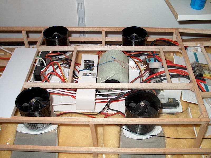
A view on the electronics : the three ESCs are on the left, switches and receiver in the center, while the steering and servo controls (for the doors for example) are on the right.
This servo operates a system to control both doors. The main difficulty came from the limited space available to install the mechanism, and from the misalignment between the door hinge axis and the skirt hinge axis toward the rear.
The last servo controls three cables connected to the three steering fins. At this stage, I’ve mounted them loosely, without connecting them yet. Since the steering fins are part of the superstructure, their construction will come later.
All three batteries are set at the front to balance the overall weight. Their final mounting won’t happen until the end, once their ideal position is determined during the last trim adjustment tests on the Zubr. I’ve designed a support that allows their position to be adjusted without needing to cut an additional hatch.
After numerous static tests—some focused on aligning motor thrust (fairly easy), others on adjusting door openings (much more difficult)—the big day finally arrived. Three fully charged batteries, brand-new power packs, and... it seems to work quite well !
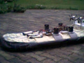
To steer the Zubr, you have to manage the three propulsion motors individually.
On the right stick of the radio, I put the motors right and left. On the left stick, I put the central motor and the steering. Without the fins, the Zubr heads easily thanks to the motors. At full speed, the ailerons will steer it without losing any thrust.
One beautiful September evening, we met by the water’s edge. A few static tests to check the controls, and then I placed the Zubr in the water. Of course, the platform wasn’t perfectly level, and after a short run on the surface, I brought it back to shore to rebalance it by adjusting the battery positions.
The separate control of the three motors makes the Zubr extremely maneuverable, both forward and in reverse. Although not yet fitted with its propeller shrouds or steering fins, we estimated its top speed at around 25–27 km/h.
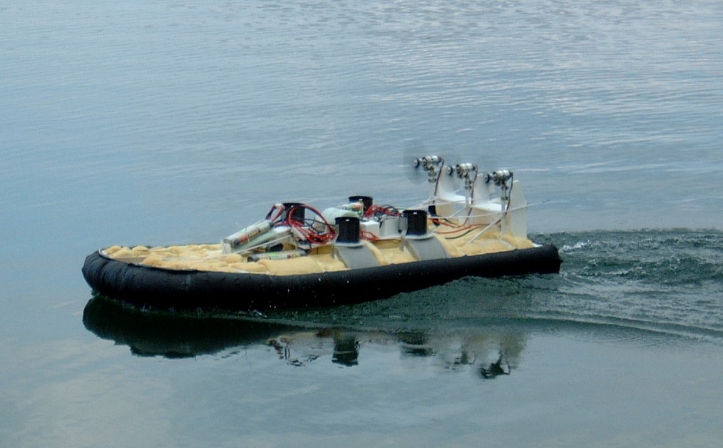
Water test - if the steering fins are not mounted, that doesn't stop him from behaving like the real one.
Contract fulfilled for my part ! Now with Didier my teammate, we're going to tackle superstructures. And there it was another funny story...
SUPERSTRUCTURES
From this point on, I hand the pen over to Didier. He carried out an impressive amount of work with a level of precision and patience that I truly admire.
The first essential step is to put yourself in the shoes of a hovercraft pilot. This helps you understand—and take into account—the major differences between building a boat and building a hovercraft, especially when it comes to weight. And that’s no easy task.
Based on the available information, photos, and plans, it was necessary to rework the dimensions—a tricky process, since the plans aren’t always to a consistent scale. So I chose to use a balsa wood structure, and for the decks, I initially went with 0.75 mm thick plastic.
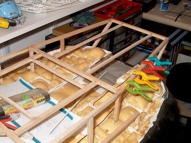
Balsa structure - balsa cleats (10mmx10mm) are glued and embedded in neoprene, to the expanded foam base from the bottom of hull. The hull takes shape from there.

First try for the deck (plastic sheets) and first try as well for motor supports, using collars.
That turned out to be a mistake. While plastic card works fine for small parts on models, it’s not a good solution for a large vessel. A thickness of 1 mm—or even 2 mm—would have been better, but in this case, the total weight would have been too high. Although 95% of the deck was completed using plastic card, I went back and rebuilt the entire main deck. To prevent warping, the plastic was reinforced with a lightweight balsa base.
The underlying structure remained unchanged. It consists of 10×10 mm balsa battens, glued and embedded in neoprene into the expanded foam base at the bottom of the hull. On these “pillars,” we glued balsa crosspieces to shape the deck.
The upper deck is now made from 0.75 mm plastic card, topped with a 1 mm balsa sheet.
All of it was sanded, sanded again, and sanded once more to achieve a smooth, even surface. The vertical sections and the deck along each side of the boat will still be made from 0.75 mm plastic card.
The lift motors were protected during sanding and painting. Their edges were formed using Milliput, then sanded and re-sanded to create a smooth, rounded profile that facilitates airflow. Now, it’s time to build the protective grilles for these motors.
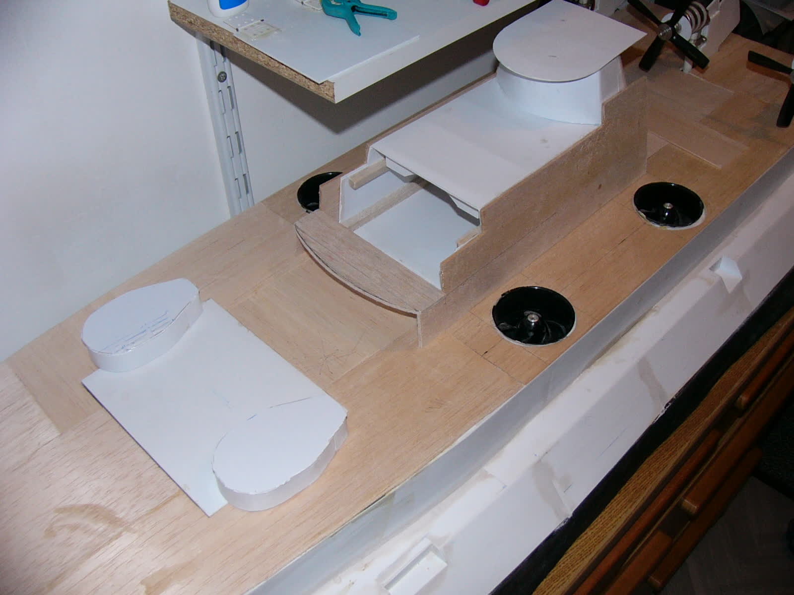
The final deck - a plastic / balsa sandwich, lighter and solid. The vertical parts and the sides are made with 0.75mm thick plastic.
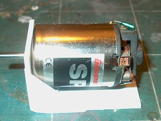
Motor support - the first collars were enough for tests but did not allow the assembly of ferrules. It took several tries to have a good result.
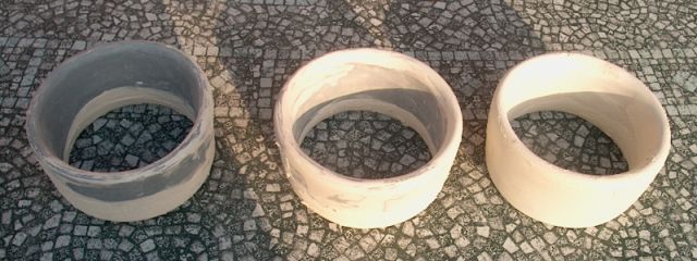
Ferrules - a lot were broken during production or during the tests. A total of 20 were made...
PROPULSION
This part posed a major dilemma. To achieve a proper assembly of the propulsion units, the motor mounts had to be redesigned—always keeping weight in mind. After several tests, I settled on aluminum supports. The motor brackets are currently under construction.
As for the nozzles, the choice was difficult: balsa or synthetic foam? For greater flexibility and lighter weight, I ultimately chose synthetic foam. A rough initial shape was carved, followed by careful adjustments to achieve the correct form. However, this very lightweight material caused me a lot of trouble. The first nozzle, nearly completed, broke during sanding.
To avoid the same issue again, I coated the surface of the nozzles with body filler (Sintofer), and the sanding was done in small, gradual passes—very time-consuming, I admit.
THE COMEBACK
I handed the Zubr over to Didier in 2006. Things went well for the first few months, and work on the superstructures had begun. Since I was also occupied with my larger hovercrafts, I trusted my colleague to carry on. Unfortunately, life’s ups and downs prevented him from making progress. From time to time, we’d cross paths and he would reassure me with a promise to resume work the following month.
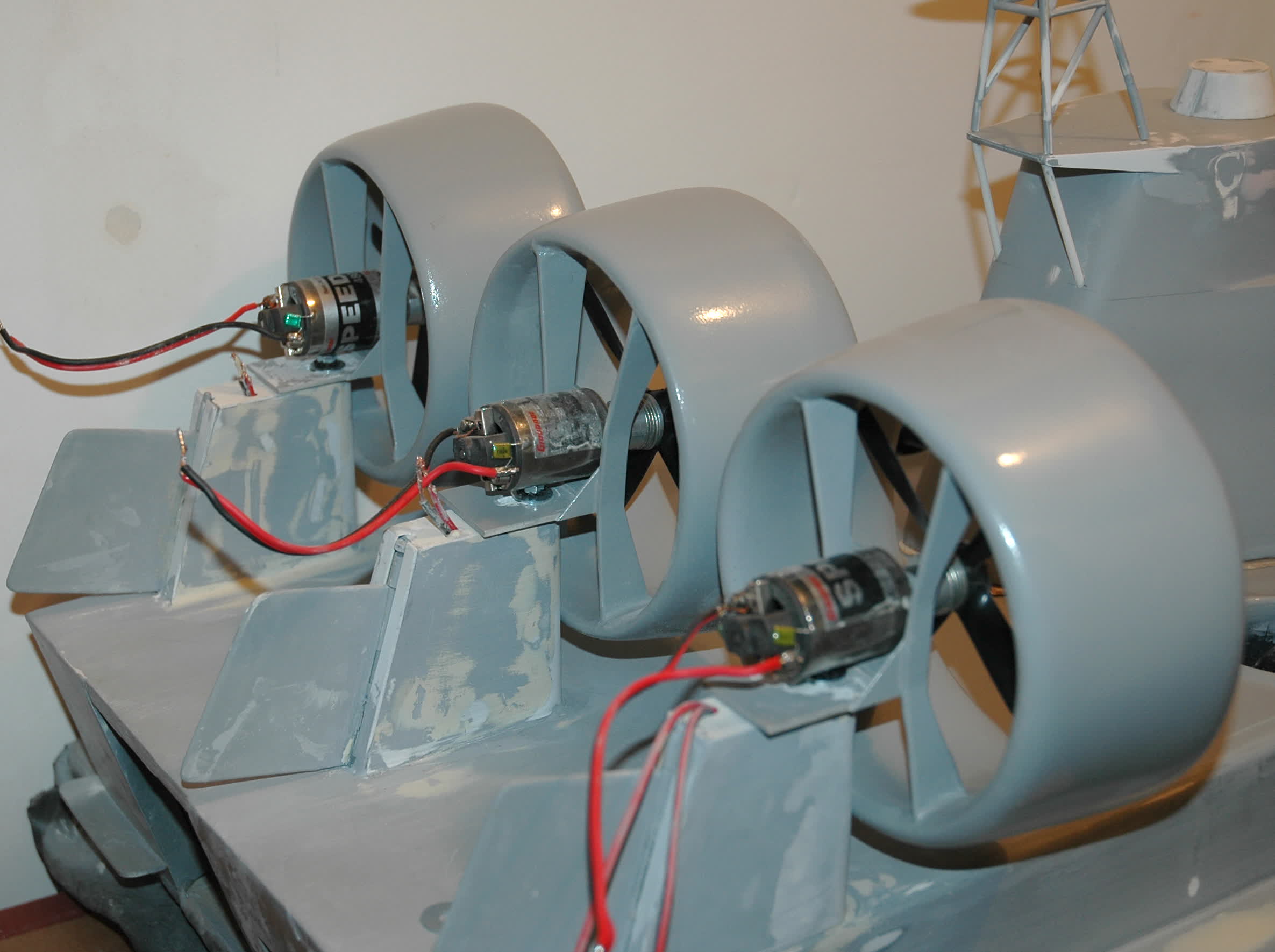
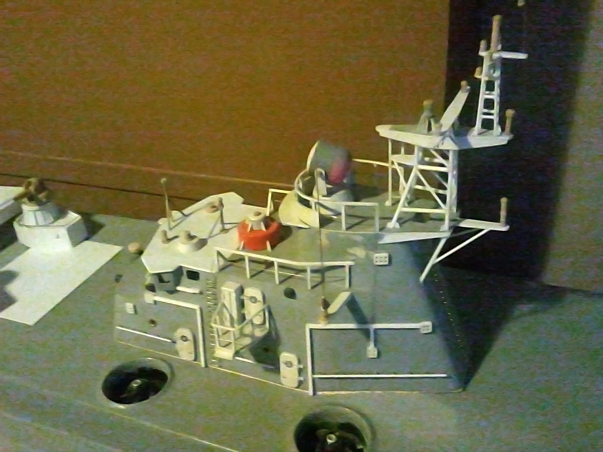
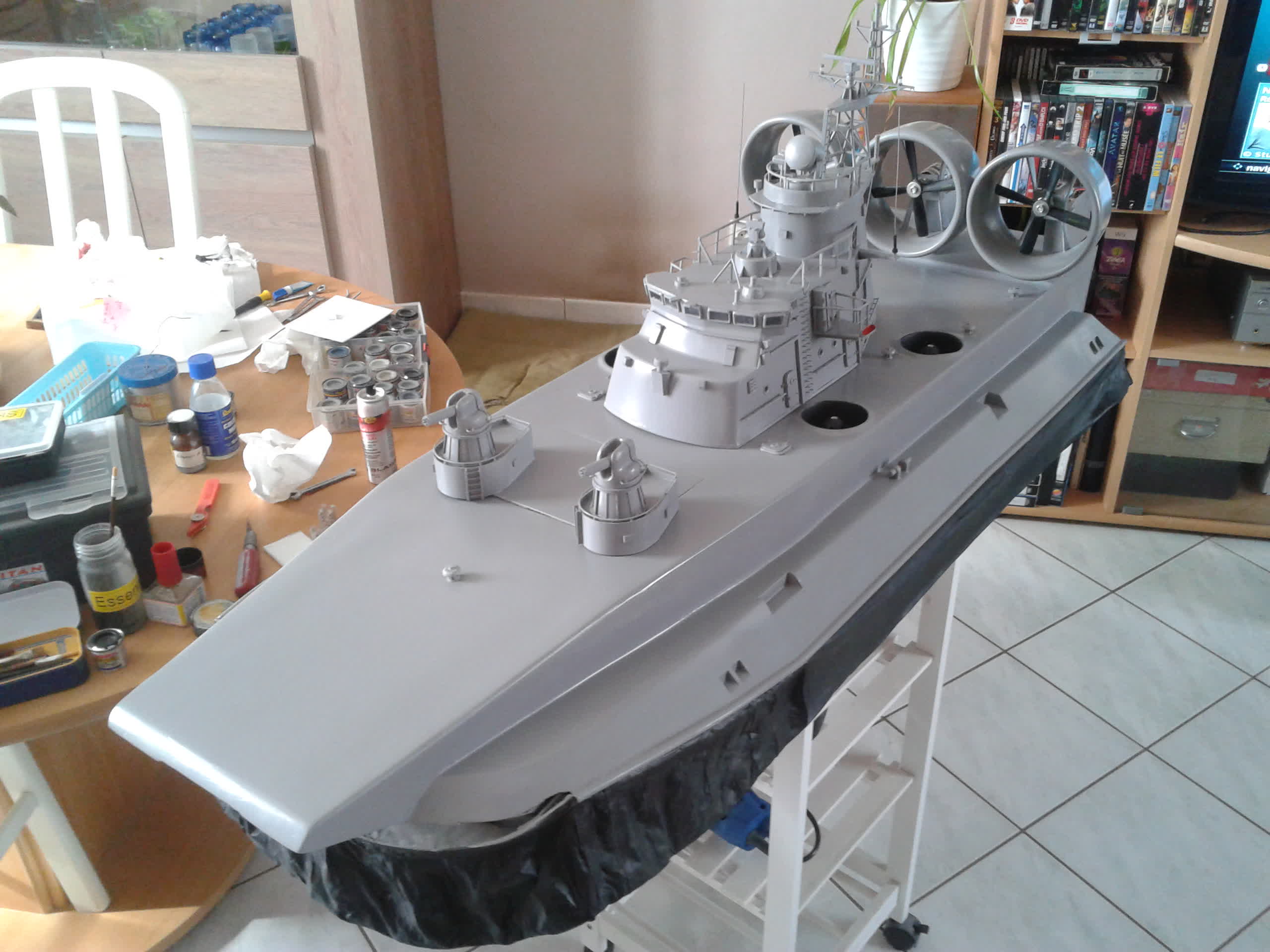
If the island and front attachments are well crafted, many details are still missing :
- The railings and protective grids for the lift motors have yet to be added.
- The propulsion motors are not functional.
- The control surfaces are blocked, for ease of construction.
- The skirt has suffered from lack of use: I can see parts loosening.
- The rear door is under construction but not yet assembled.
When I lift the Zubr, I realize just how heavy it is. Although a hovercraft operates on water, its construction is more like that of an aircraft: weight is the enemy. On the scale, it weighs 8 kg, but it should not exceed 6 kg to remain realistic. To reduce weight, I’ll have to remove some material. Since the superstructures cannot be dismantled, I’ve decided to work from underneath.
.JPG)
First step : repair the skirt and check its good functioning.
Second step : open the hull by cutting the bottom.
Fortunately, I kept pictures from 2003. I could cut through without taking any risks. I'm going to cut two long strips and take out all the accessible buoyancy foam. I will replace it with ait bubbles used to wedge fragile objects. The hatches on the top do not give access to the entire electronics - I will relocate them as well.
.JPG)
Third step : remake the electronics layout.
There are the three ESCs for thrust, the steering rods for the two doors, and the electronics for the lift EDFs. In 2003, I used 3 heavy NiCd batteries - but today we got LiPo batteries. I will take advantage of them to reduce the overall weight.
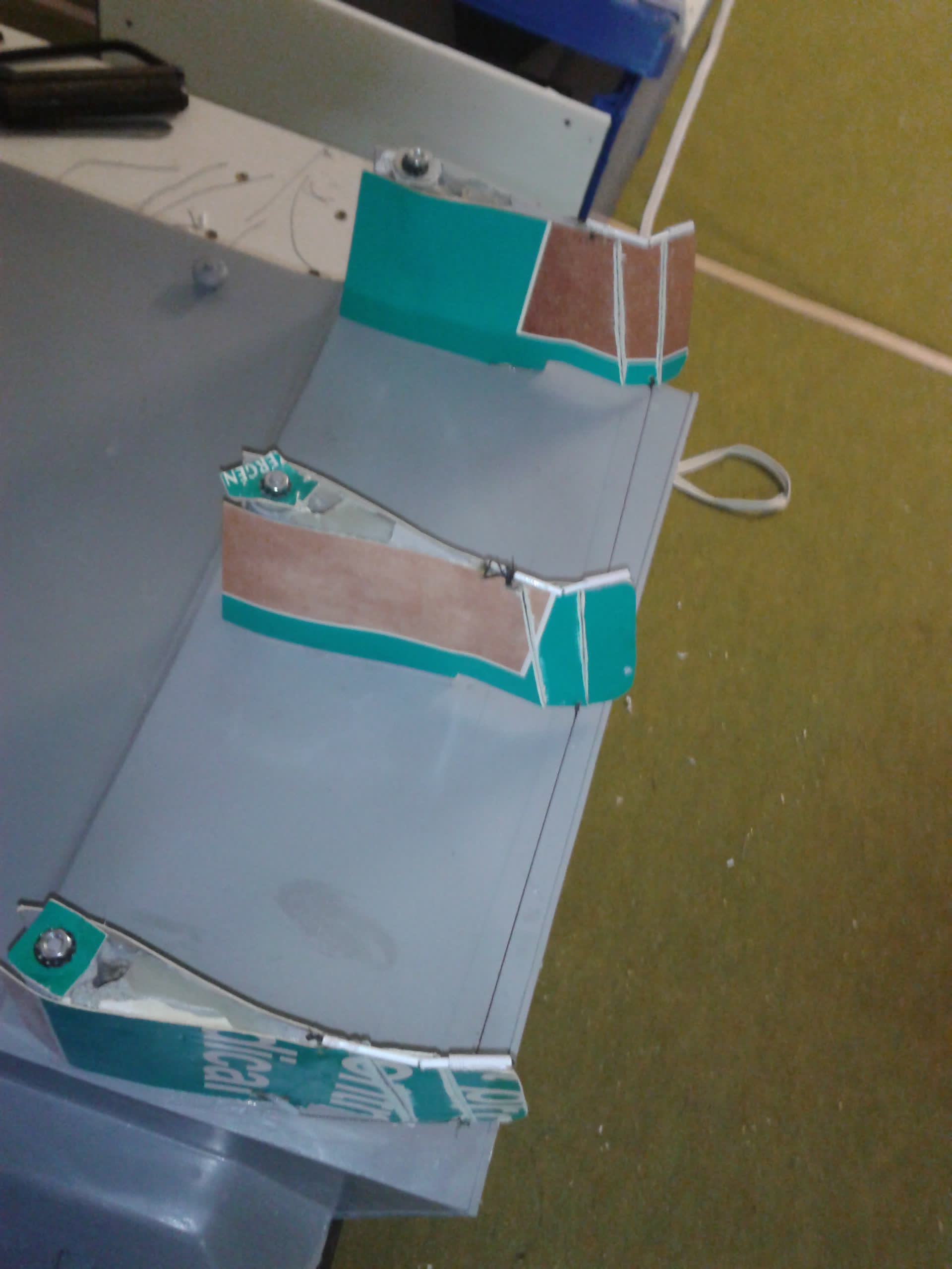
To begin with, I focused on the rudders. They were fixed, which wasn’t satisfactory. On the real craft, they consist of three parts: one fixed and two movable. After several unsuccessful attempts to create rudder planes, I did some research on my favorite website and found the concept of the Becker rudder in an article about rudder control. I now needed to adapt that concept for my own use.
After several drawings and sketches, I made a first prototype, which turned out to meet my needs.
On the picture, the three steering flaps, made of recycled cardboard
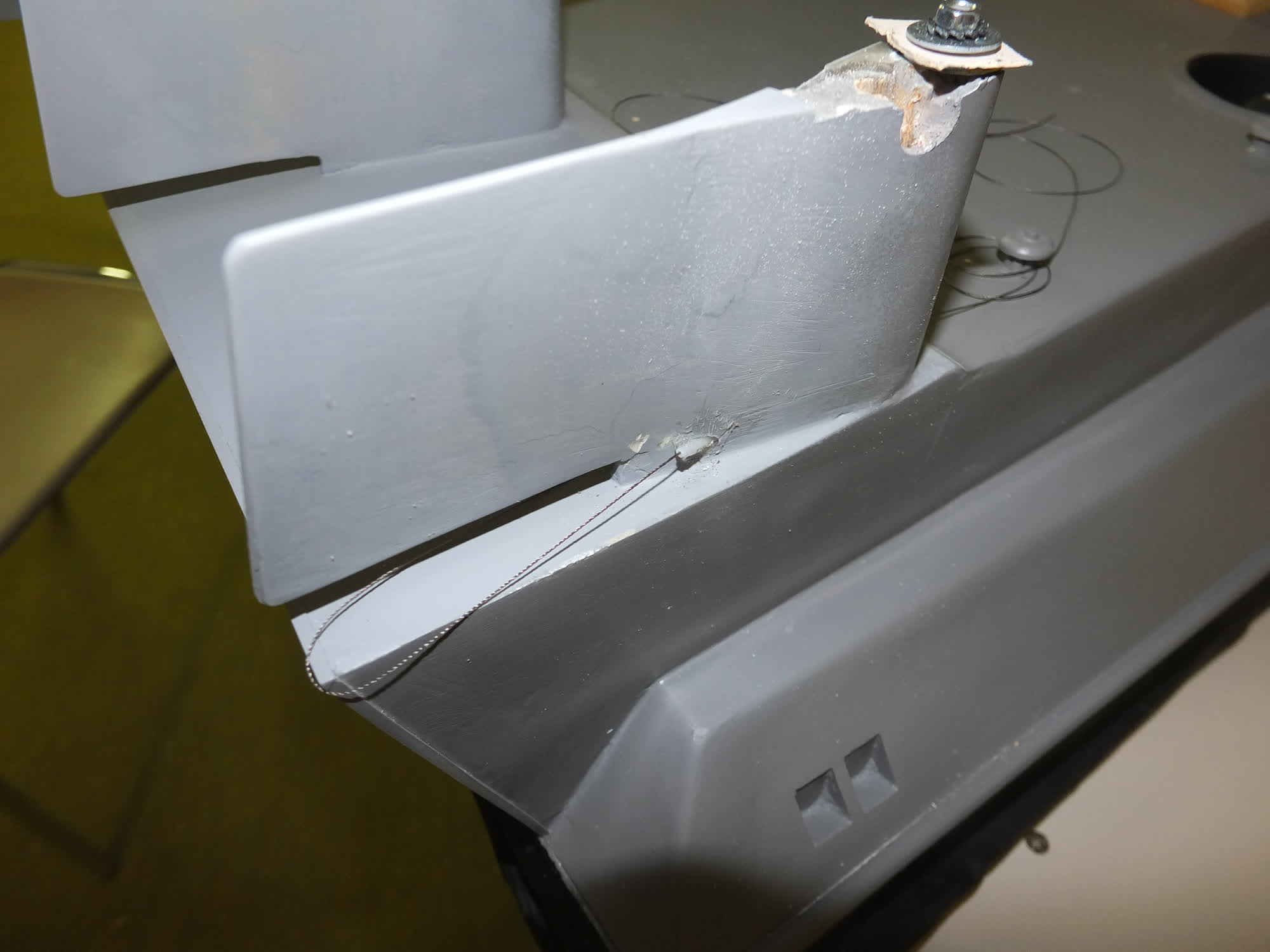
In this photo, the shutters are still attached, but I’ve already passed the control lines through. To do this, I use sewing thread—the same kind I use to repair the skirts of large hovercraft. It’s very strong and runs smoothly through the small plastic tubing. I install one line on the port side and one on the starboard side, then connect all three components with a common line. This way, the servo will always operate under tension.
I mount the servo as far forward as possible to help with weight distribution, and I add tensioners to the lines. They’re very simple—essentially replicas of the ones used for tent ropes.
Then begins a long adjustment phase. The tension level is crucial for everything to function correctly, as is the precise placement of the tension points. I had to redo the hooks on the outside of the port flap several times before achieving smooth operation.
THE REAR DOOR
Since the cardboard I salvaged from the pharmacy gave good results (it’s laminated on one side), I use it for the rear door. I build up a sandwich structure to get the desired thickness and shape. I add a control rod and attach everything to a hinge made from a piece of skirt fabric. The result is immediately satisfying. I’ll just need to fine-tune the travel later, once the front door is finished, as I want both doors to be operated by a single control.
THE FRONT DOOR
Building the front door is far more challenging. The first difficulty: the bar supporting the skirt is broken. The second: the waterproof fabric between the skirt and the hull was painted—and it couldn’t handle it. It tore during one of my attempts to repair the front support bar. I experienced this as a real disaster. Without that fabric, the skirt can’t function—and the Zubr becomes a static display model!
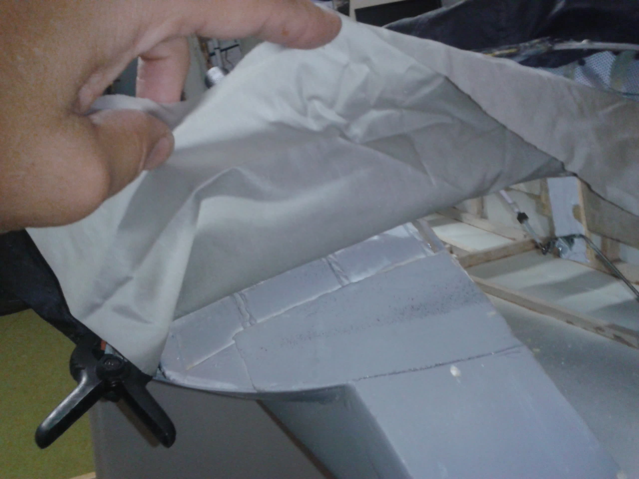
Then begins the difficult task of disassembling the entire skirt section—but luck is on my side. The black skirt manages to withstand the removal without tearing.
After a full day’s work, I finally uncover the hull and can repair the front bar before installing a new piece of fabric (fortunately, I still had some left!).
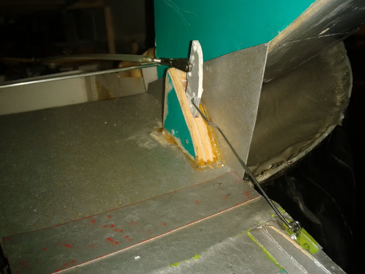
The Hinge
The original control system was lost during repairs, so I’ll have to completely redesign the door hinge. With the superstructures in place, I now have better access to key areas—but that also makes things more complicated.
After several tests, I develop a double hinge with differential control. It’s not entirely true to the original design, but it looks better overall. Since I have extensive documentation on the Zubr, I keep comparing the model and the full-scale version throughout the process.
I couldn’t resist adding the chains that support the real Zubr’s door. In reality, the doors are operated by hydraulic cylinders, and the chains are only used as a backup. Still, I decide to include them on the model.
On the first attempt, they jam and block the doors. The solution: make them functional.
Using old cable sheaths and skirt wire, I create chain guides that connect to an extended arm on the servomotor.
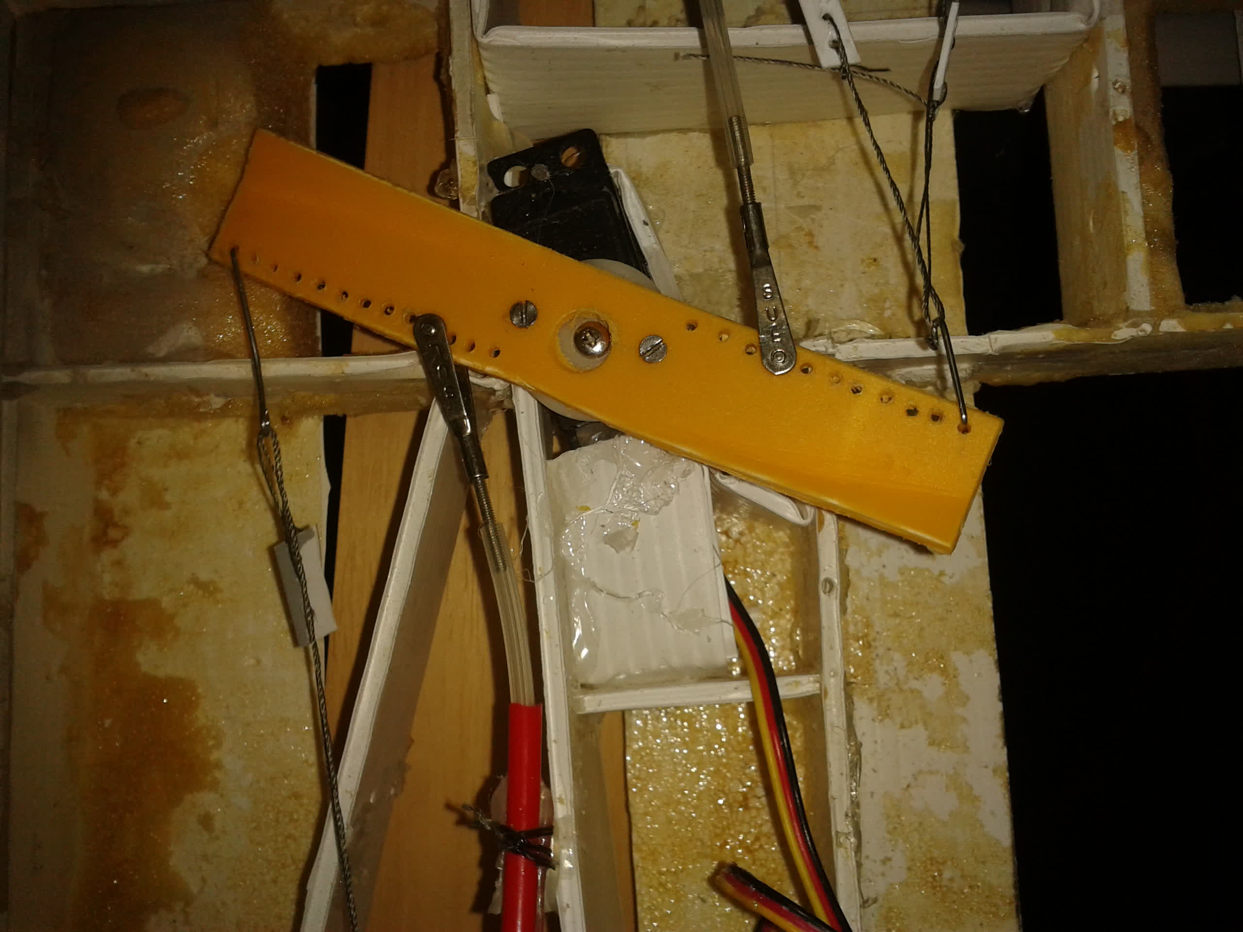
We see the tensioners identical to those of control surfaces. A few adjustments later, I’m happy to see everything working.
FERRULES
Didier’s ferrules are beautifully made, but at 115 grams each, they leave the Zubr with too much weight at the rear. Unlike boats, which may require ballast for proper balance, a hovercraft needs to stay relatively light, with well-distributed mass in order to fly properly. I’ll try different techniques to reduce their weight. After experimenting with heat-formed polypropylene, I decide to abandon that approach.
I just can’t get the right fit or the rigidity I need. It’s certainly lightweight, but it’s impossible to reproduce the various parts reliably. Remembering the paper-pulp molds I once made, I try creating a prototype with that method—but it turns out poorly.
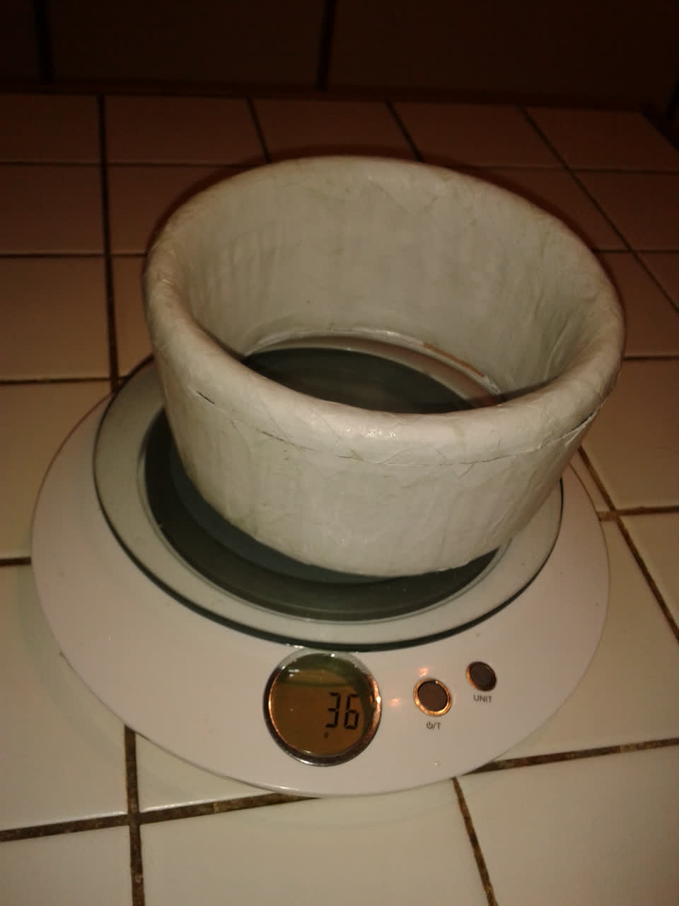
Still, I can see the potential. It’s light, and with two crossed layers, it becomes rigid enough. I talk about it with people around me, and a friend brings me some glue she uses at school. Paper glued with varnish glue turns out to be the easiest method to work with. After a few attempts to refine the technique, I manage to produce a 36-gram ferrule, including the inner cardboard reinforcement ring.
And the icing on the cake: I manage to make three identical ones, with just a few small differences. The fit with the propellers isn’t perfect, partly due to the paper’s thickness. I’ll adjust their diameter later when I glue the internal uprights. But first, I’ll move on to building the motor nacelles.
The motor nacelles
Once again, I’ll spend quite a bit of time figuring out how to make them. My main enemy is the weight at the rear. Paper models glued with varnish require an internal structure, which makes them too heavy. Sculpted foam models look nicer, but they’re still too heavy.
So I decide to create a polypropylene mold using a bottle. Bottles have an almost ideal shape, and the plastic shrinks well when heated. I’ve never drunk so much sparkling water as I did during that period!
I manage to make about a dozen molds. Unfortunately, the bottles are either too small to get both the front and back properly formed, or too large and don’t shrink enough. I end up making a hybrid, combining a well-molded front with a properly shaped rear. The technique is simple: I placed one of the foam models inside the bottle before heating it.
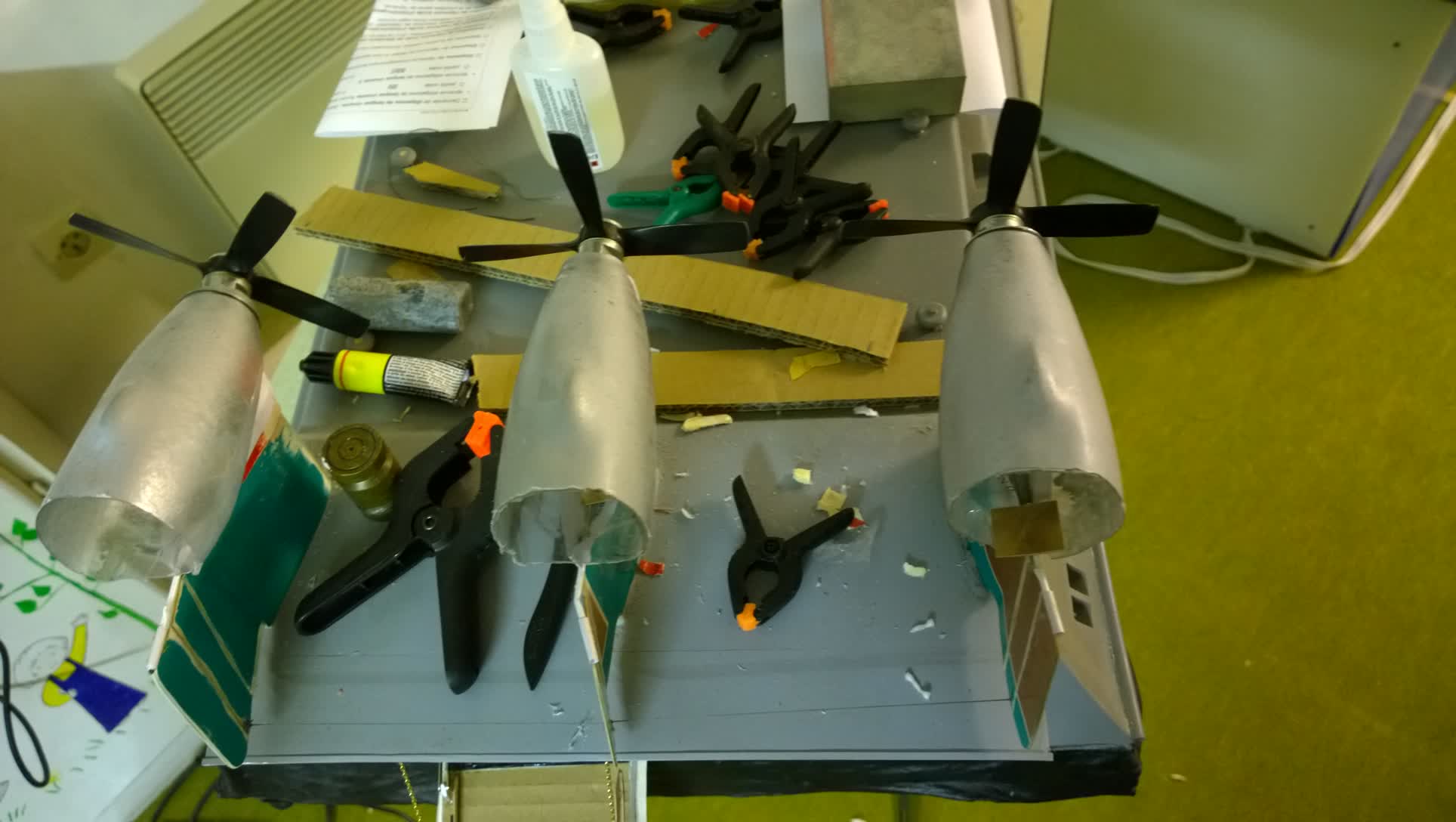
The three front pods - Before assembling the two parts, I make the air intakes, which I want to keep functional to cool the motors. I’ll seal them using paper and gloss glue varnish. For the guardrails, I used the same type of wire as for the control surfaces.
I glued it in place with gloss glue varnish. Once it stiffened, I secured it with a drop of UV-curing resin, such as Soliq.
Judging by some of the builds featured on Navimodélisme, I still have a lot to learn — my level of finish isn’t quite there yet. At this stage, I tested the motors, and they responded perfectly.
Just like on the real model, I make the ferrule supports underneath, then glue the ferrules in place, aligning the propellers all around them to ensure proper centering.
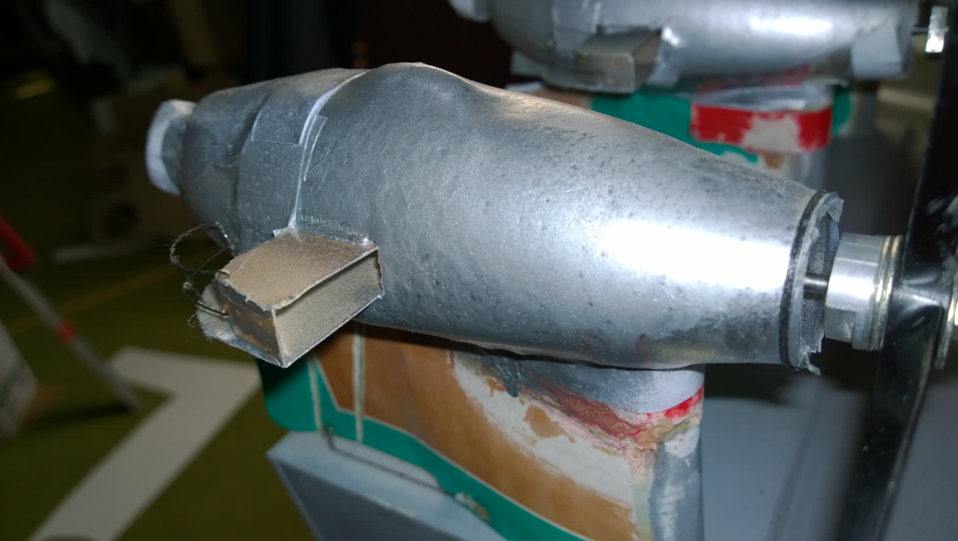
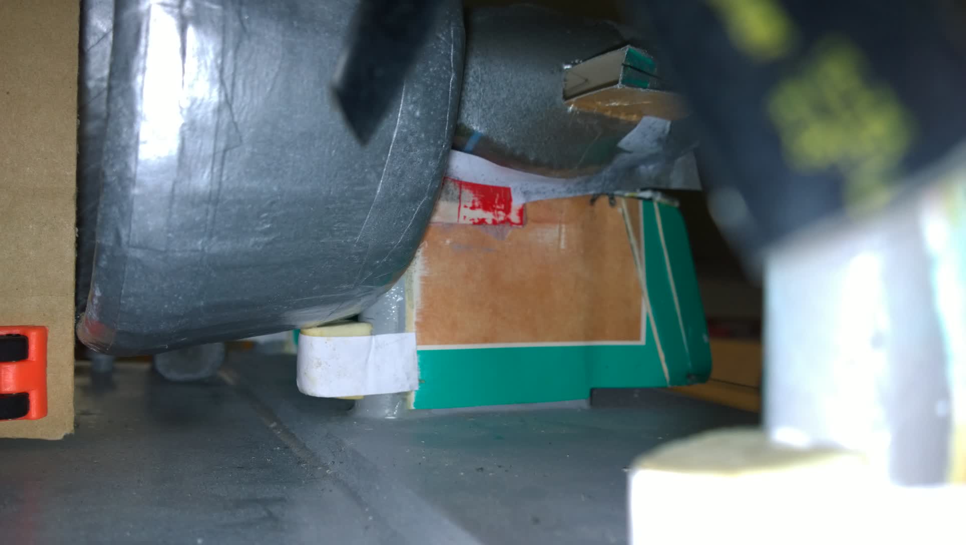
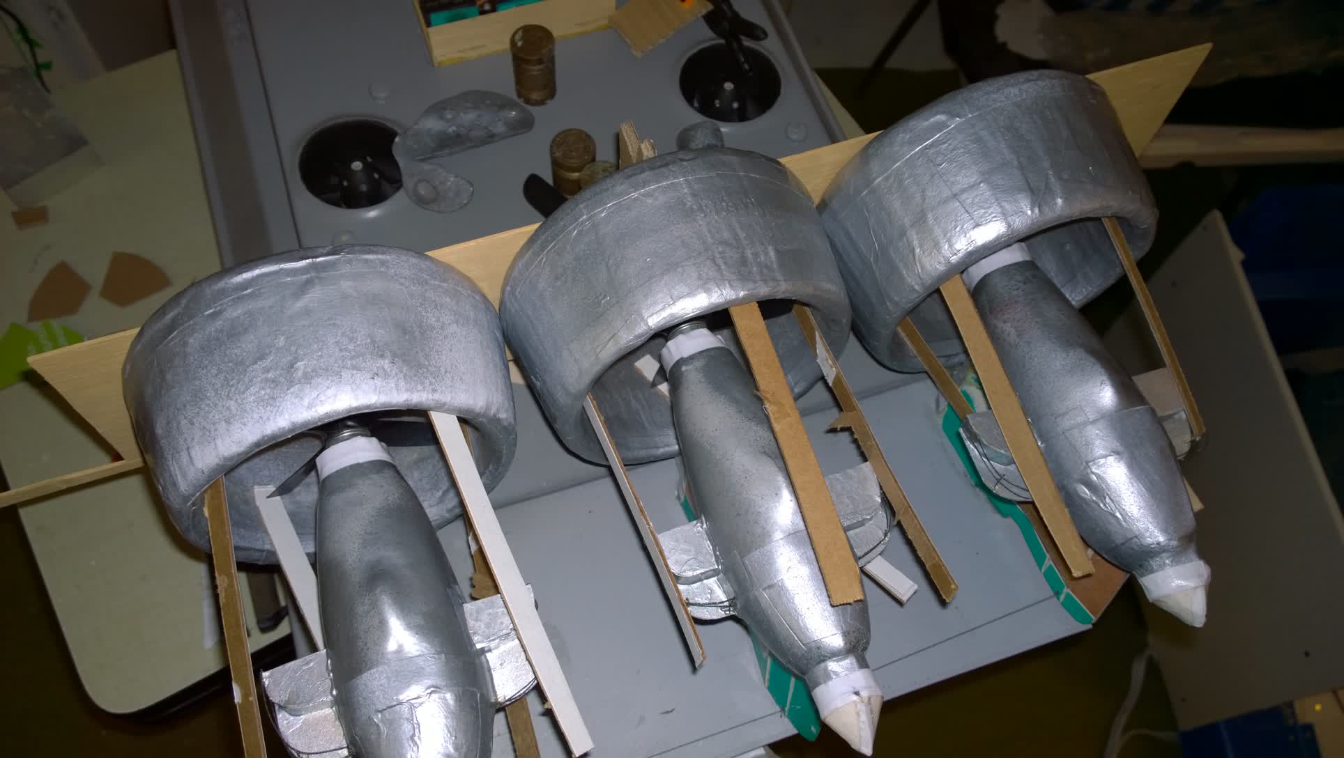
Last step : the internal stiffeners, made with thin corrugated cardboard, opened in half at both ends to improve support.
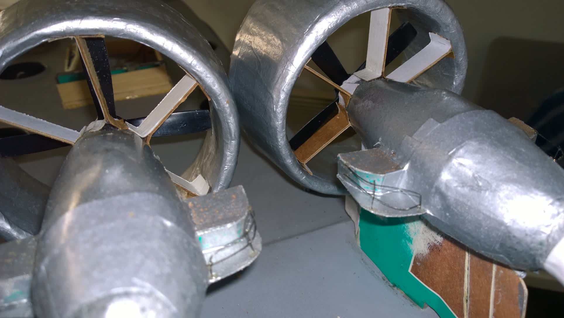
View of the rectifiers - When everything is dry, new tests were made, giving good resulst. The propellers rotate without hurting anything.
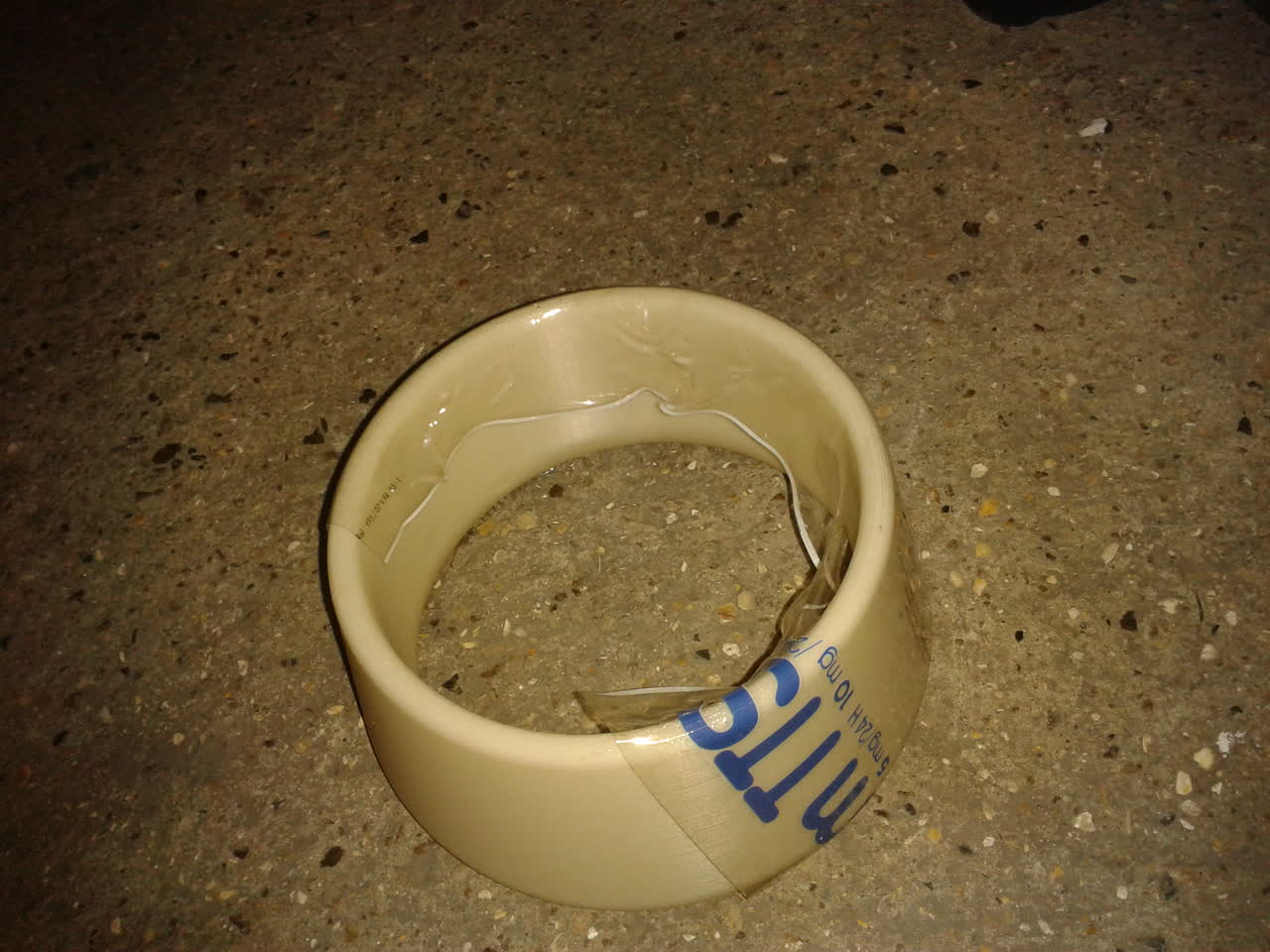
First ferrule made of paper : 36 grams
Nacelles draft made with foam
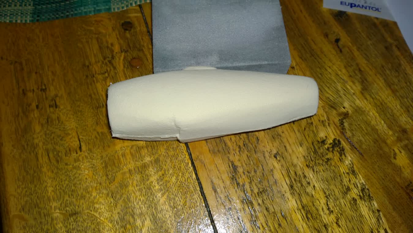
Nacelles draft made with foam
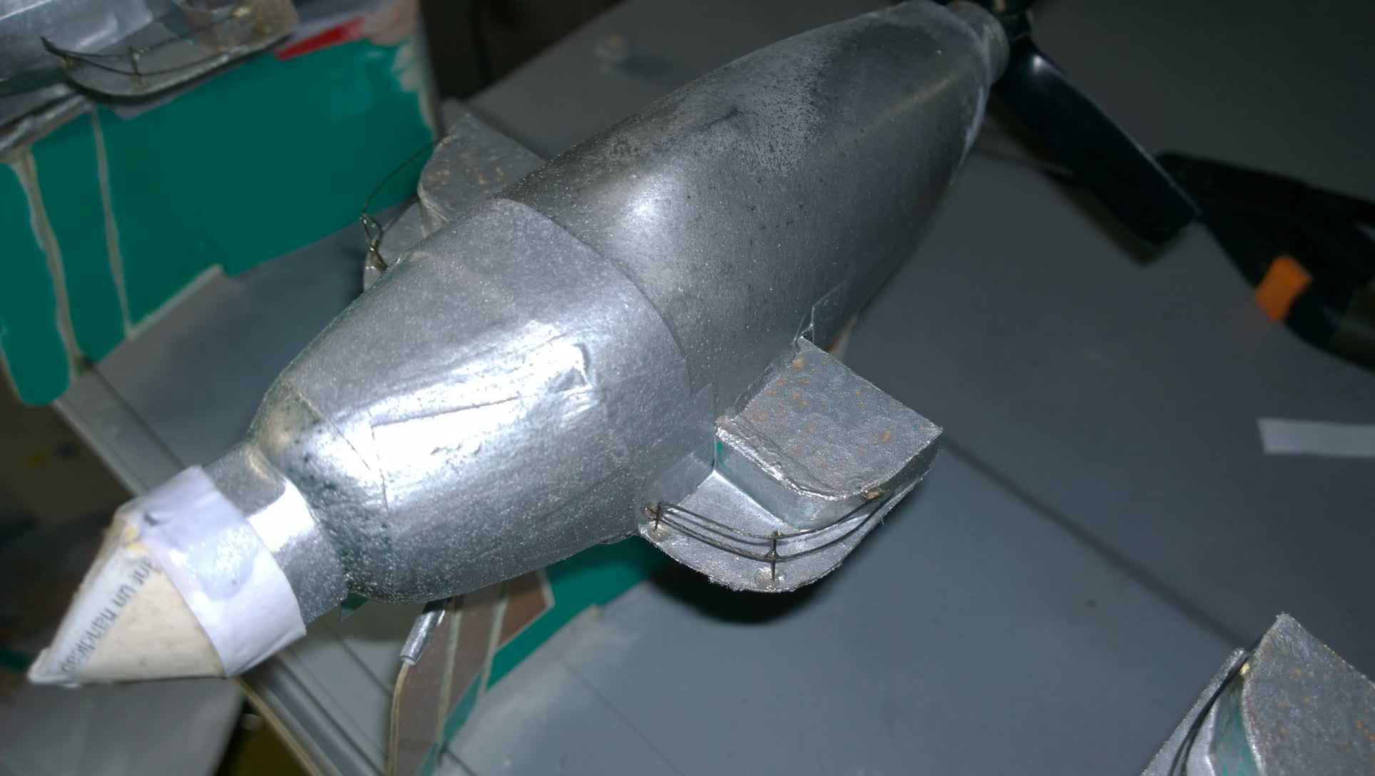
Shaping the nacelles
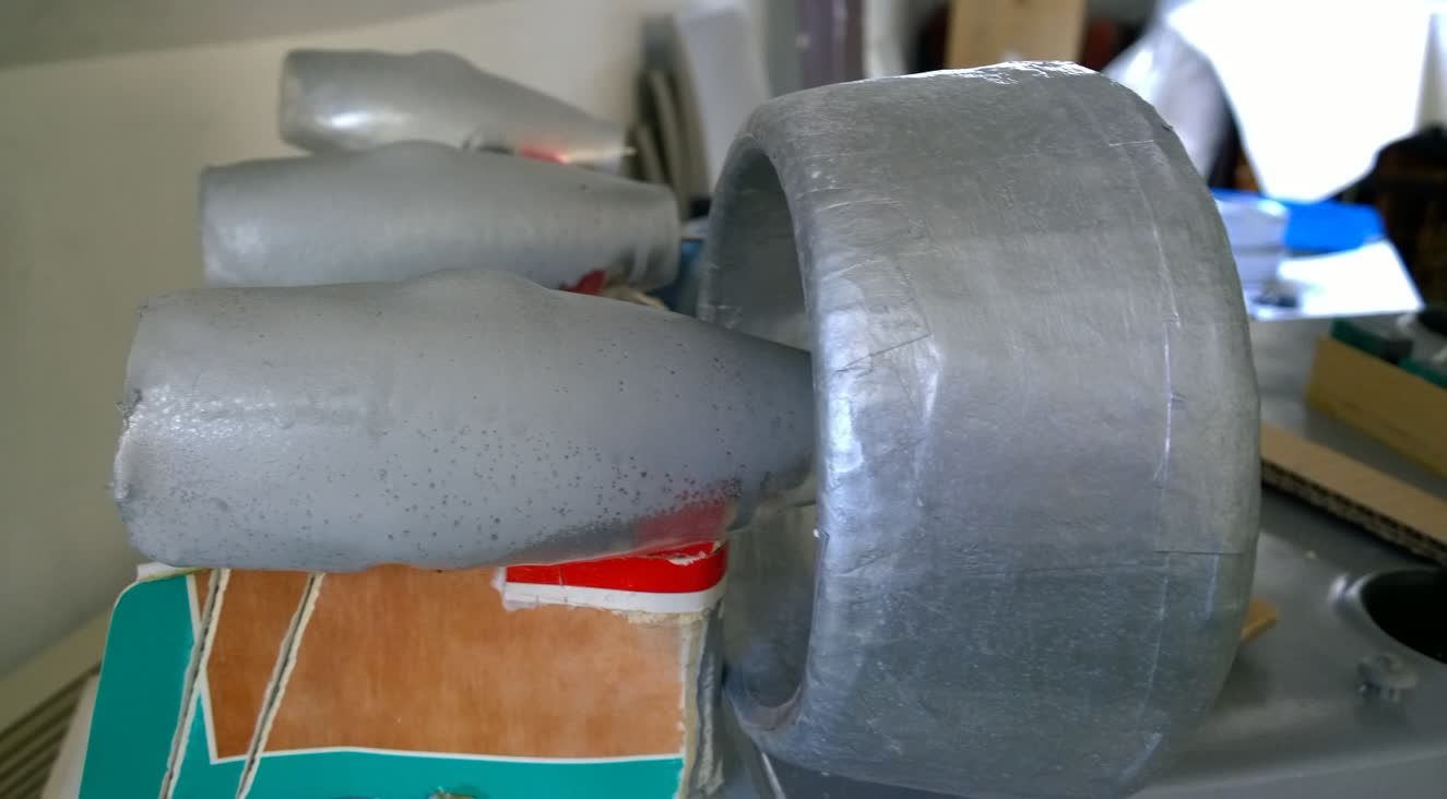
Before nacelle and ferrule test
FIRST TESTS
Of course, there were some problems with the radio control, which had been stored for too long. I’ll have to replace the battery holder, which only stays in place thanks to repair tape. Still using duct tape, I sealed the bottom and did a first “real” test on my terrace.
The result is mixed: it lifts off and moves forward, but the rear is still too heavy. Back to the workshop, where, after removing the skirt, I took out more foam from the back. The Zubr thus lost 150 g. Once everything was closed up, I weighed it: it now reaches 6 kg in working order, including the battery.
New tests. The balance is better. After adjusting the battery position—because it leaned too much to port—it now goes straight and maneuvers correctly. But the rear remains too heavy. So, unfortunately, I had to add weight at the front. I tried with 150 g, then 300 g. On land, the addition of 300 g at the bow balances it well and makes it manageable… if we can say that about tests done in a space that is too small for such a large model.
THE ZUBR: BEFORE & AFTER
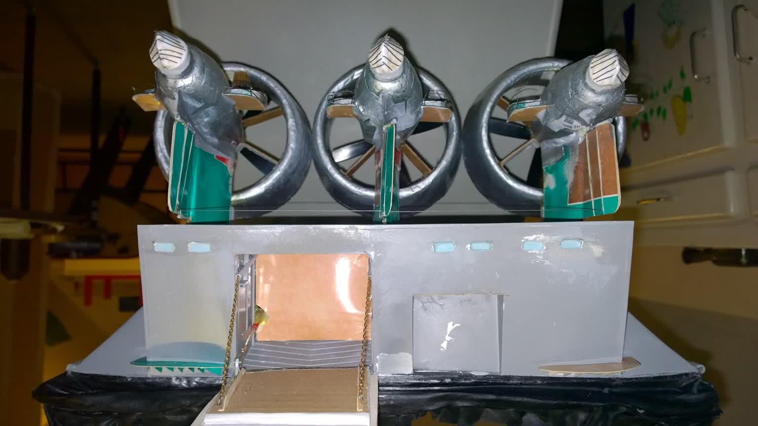
Rear: On the first photo, I had already cut out the upper openings and glued a cardboard cover behind them. Then I glued small bars made of black wire coated with glue. All the details are made of cardboard of different thicknesses, glued and coated with the varnish-glue I mentioned earlier. On either side, you can see the (closed) exhaust outlets of the lift turbines. In front of each outlet, there is a small platform supported by brackets. On the slanted edges, you can see rungs made of staples. The holes are drilled using a template and glued with Soliq, which has the advantage of setting immediately once the UV lamp is applied.
The pedestrian door, like all doors, is made of cardboard pressed on a mold, and I glued on the hinges and drilled the porthole, which will be painted black.
The vehicle ramp is operated by a cable and, as before, has two channels for decoration. The bottom is closed with cardboard. On the outside, the documentation shows some details that I add, like this circle whose purpose I don’t really know. All around, various small "legs," "hooks" visible in the photos are represented by small pieces of cardboard that will take on the color of the superstructure when painted.
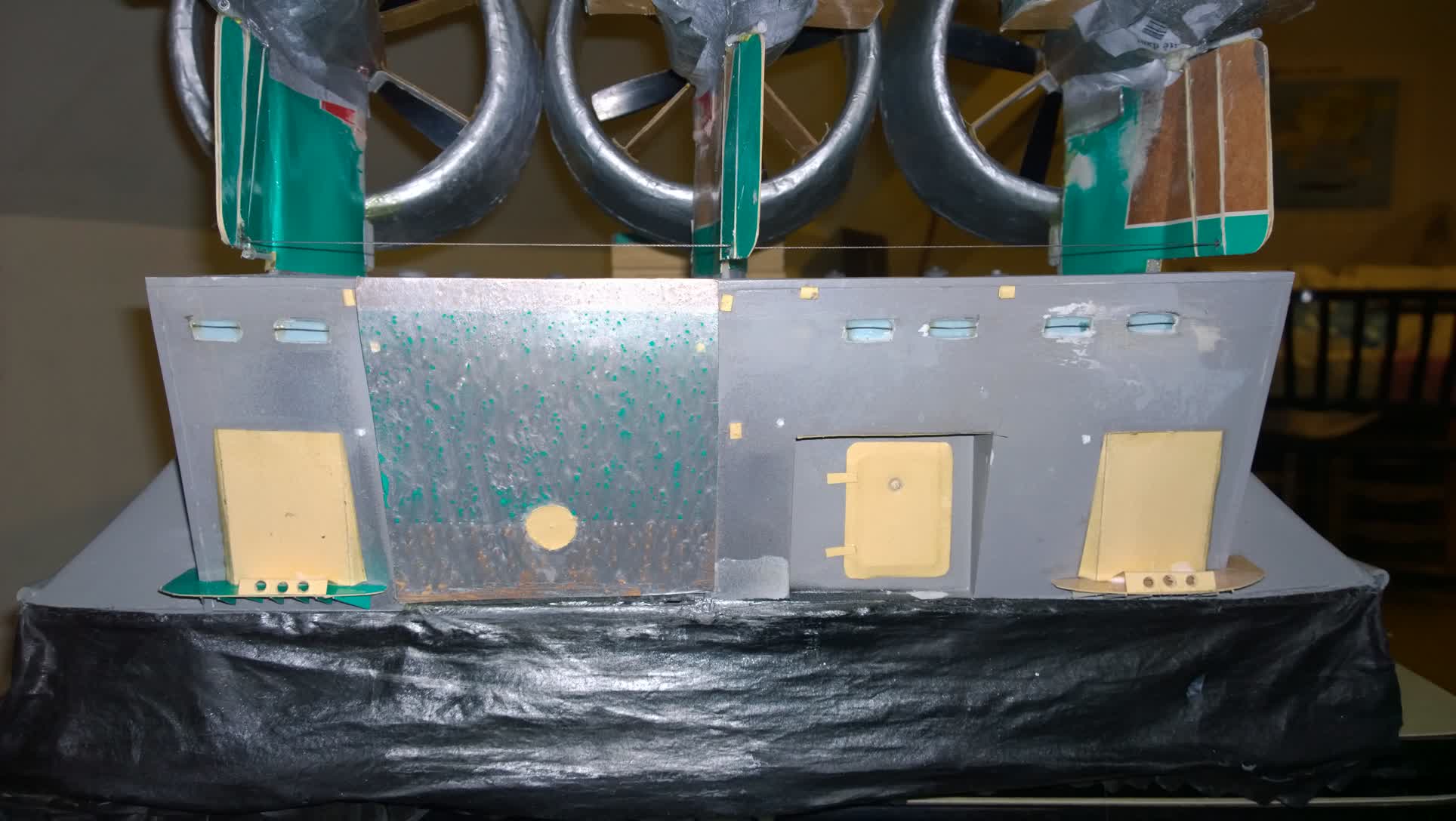
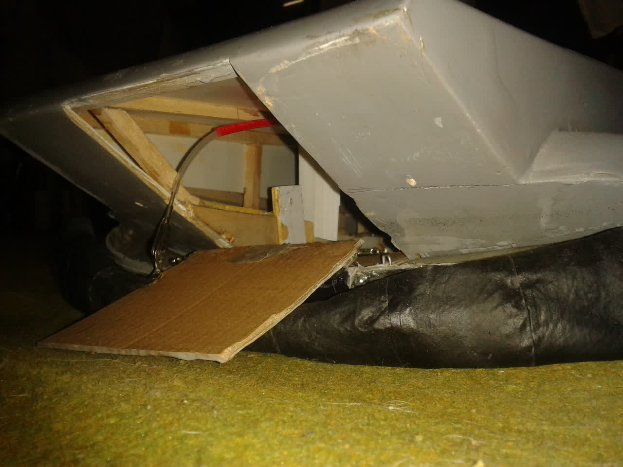
The front section is going to be reworked. According to the documentation, the hinge bar fits into the superstructure. I begin by reshaping the slopes of the bow on both sides of the door using filler, and I cover the metal bar with fabric so that I can paint it afterward.
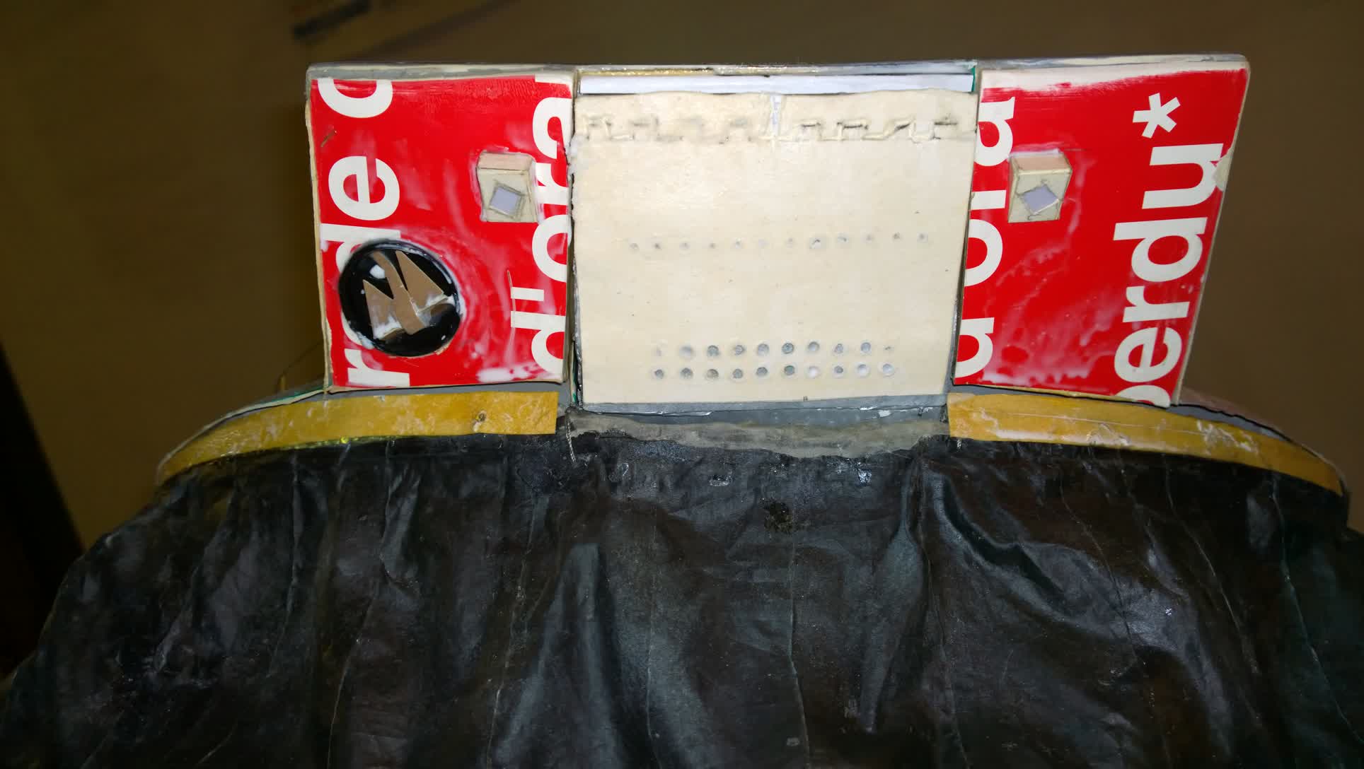
The door is covered with multiple layers of cardboard, with the topmost layer engraved. At the top, you can see the cutouts for the door’s moving parts. On two levels, I’ll add the series of holes present on the real door before gluing this section in place.
Finally, I’ll attach the two square headlights—though they won’t be fitted with lights—and I’ll repurpose a photo box lid to create the chain locker, where I’ll glue a fake anchor.
Overview: If we compare the port side with the starboard, we notice differences.
There are two doors further forward near the turbine air intake, as well as hatches and plates that do not exist on the other side.
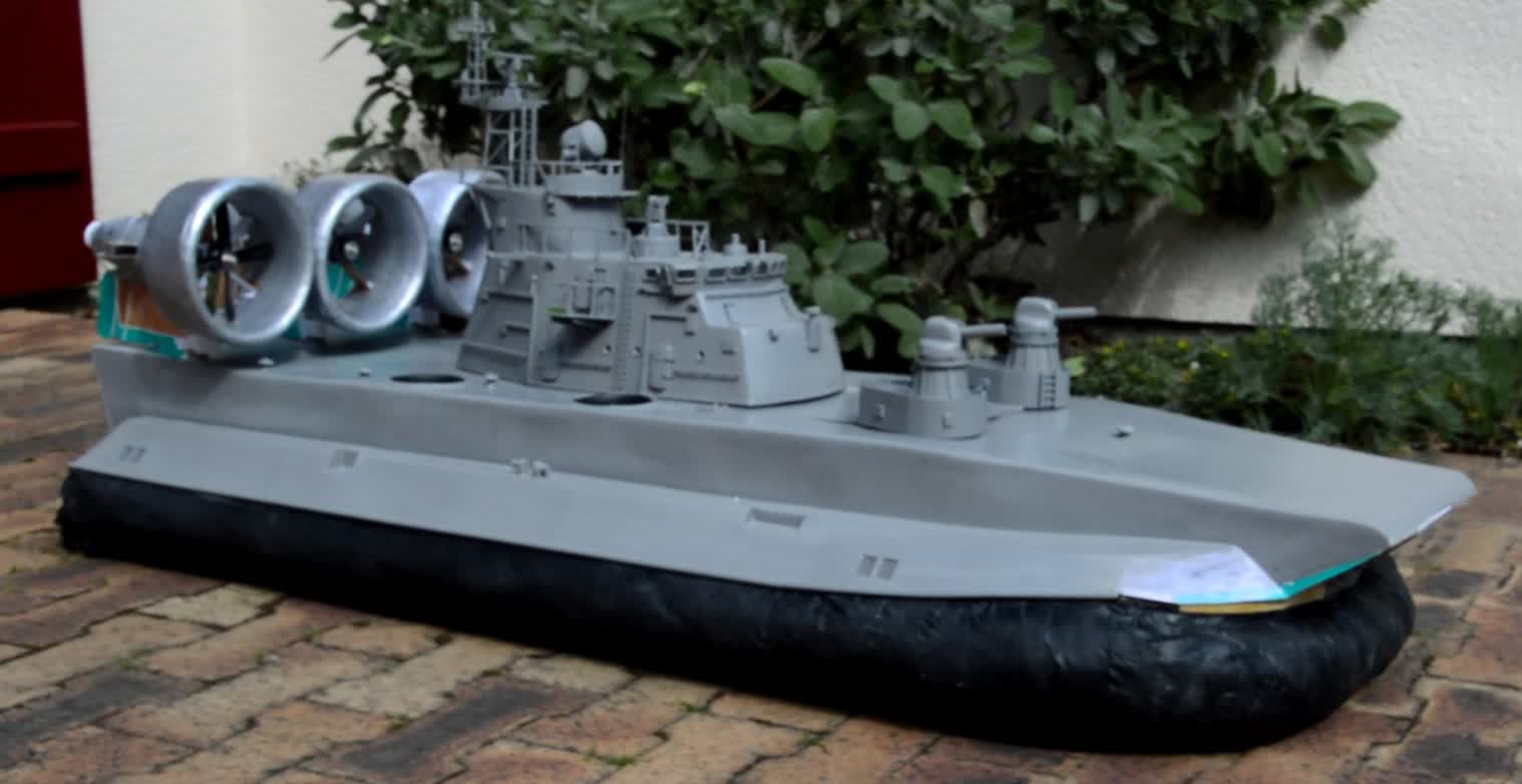
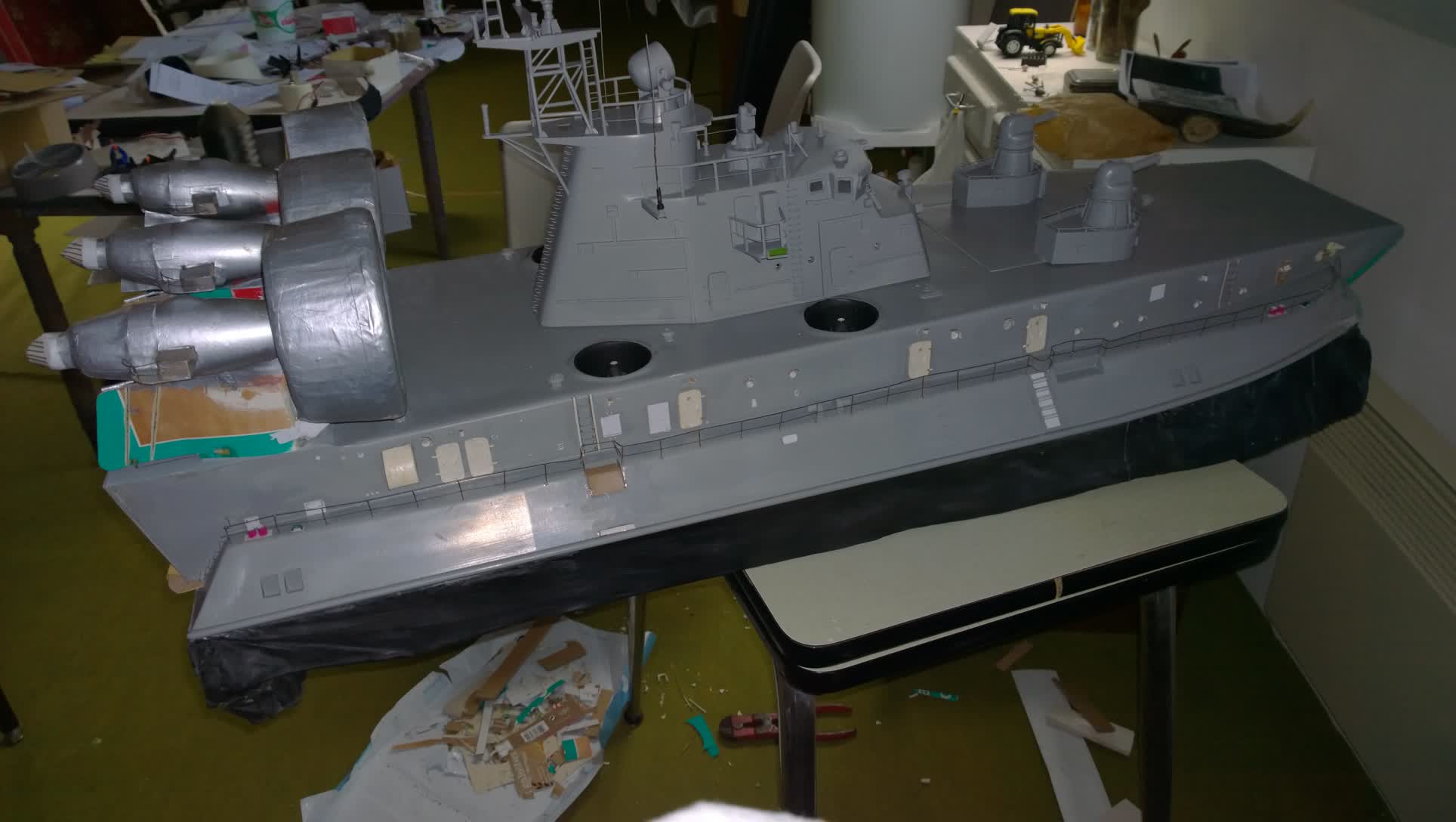
I will use the same technique to achieve all the details. There are also two recesses. The first, at the front, is used to place the emergency boat containers for the 27-man crew. I will install them at the end. The rear overhang, which was too deep, has been corrected, but since I have no documentation on what it might contain, I will leave it blank.
Little Zubr is starting to actually look like a Zubr, which seriously complicates its transportation.
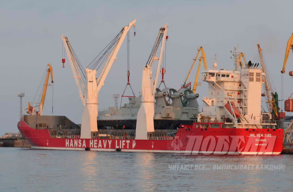
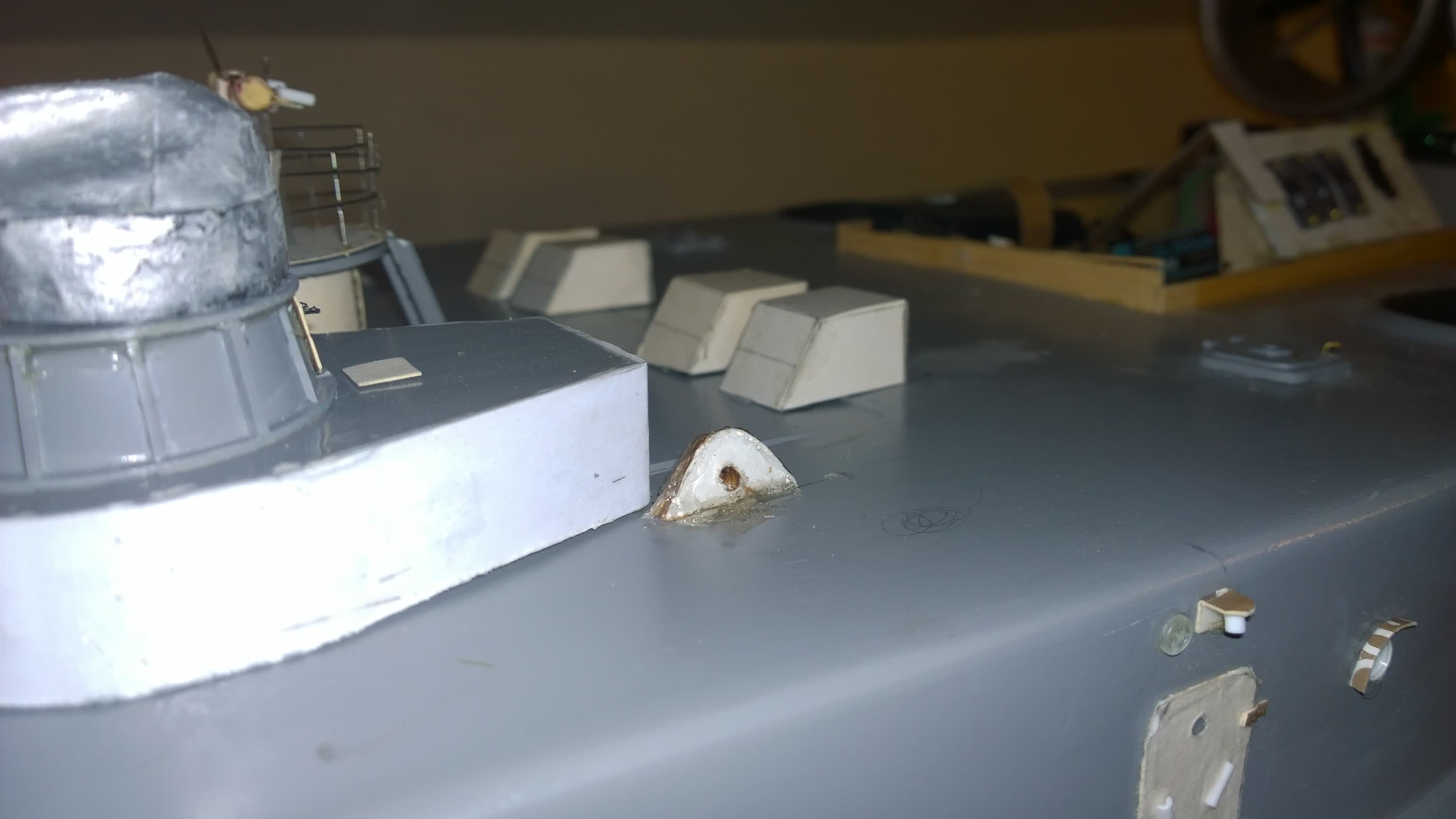
It's impossible to carry it easily without damaging a piece of railing or some detail. You need to be able to lift it properly when carrying. I remembered one of the articles from RC Navimodelism. We see a strap system used to launch boats onto the water. Unfortunately, the width of the Zubr makes this method rather inconvenient. I owe the solution to the Chinese! In a video they posted online to mark the delivery of their first Zubr, we see the hovercraft being loaded onto a freighter. That's exactly what I need. So I'll make the four deck hooks functional.
To do this, I will drill through the deck and reach the hull structure to fix steel bars ending in a loop, covered on both sides with cardboard cheeks. The most delicate part will be turning the Zubr over to peel off the bottom strips and put them in place. During the tests, it's much more effective.
DETAILS
When I got the Zubr back, it was beautiful but lacked the details that give it life. Unfortunately, I had no experience with this. I got started, learning by doing.
Always returning to my documentation, I noticed that there are several Zubr models with varying details. Looking at the island, it clearly couldn't be one of the units sold to China; on the other hand, it matched one of the four Greek Zubr. But since it was built in the USSR, I ended up choosing a specific model: it will be No. 782 “MORDOVIA”, built in 1991 by Primorsky Shipyard in Saint Petersburg, and based in the Baltic.
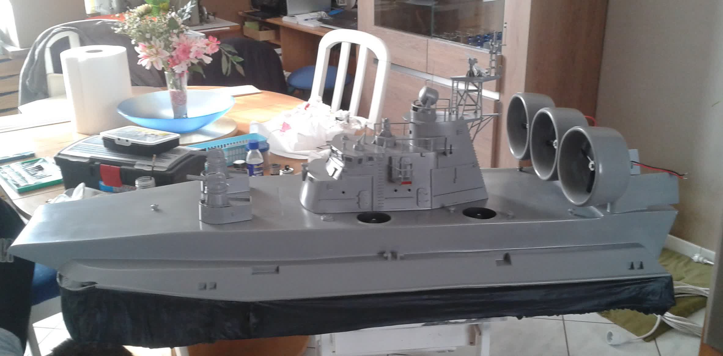
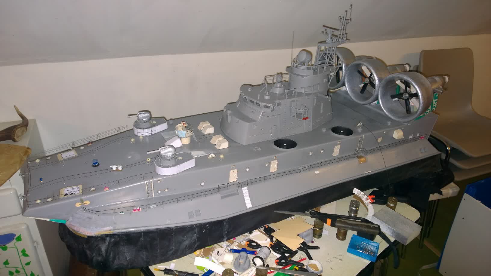
In the front view, we can see that the machine guns are out of place—I'll get back to that later. By carefully examining all the photos, I decided to pierce the sides to simulate the portholes, which I highlighted with small protective rings, and to make the doors just like those at the back, using layered cardboard shaped on a mold. The two ladders are made of staples glued with Soliq. We can also see double mooring bitts made from a mechanical pencil body with a pin to form the horizontal bar, and fairleads carved from a piece of plastic. Various hatches and openings are either glued on or carved in. They will be painted later.
I added the stairs on the sloped side. While at it, I slightly reorganized the front by gluing a partition to improve the alignment between the hull and the skirt. Finally, I drilled about forty holes to install stanchions onto which I glued stiff wire to simulate the guardrail cables. To improve the finishing, I added two small details above each door: a circle to simulate what might be a bell, and a light (unfortunately non-functional) made of a small white tube glued onto a cardboard square.
At the back, there's a rather generous half-round shape, also made of cardboard. This represents the turbine's air intake. On the Mordovia, it's wide and singular—on other models, there are two smaller ones.
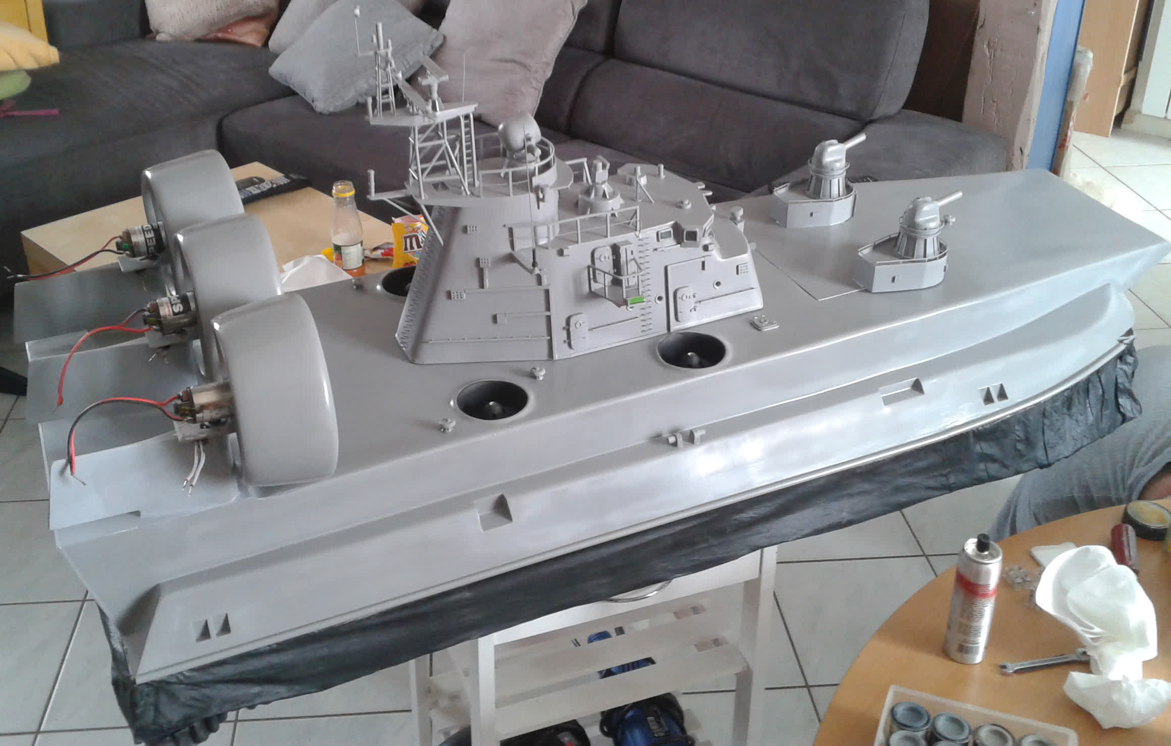
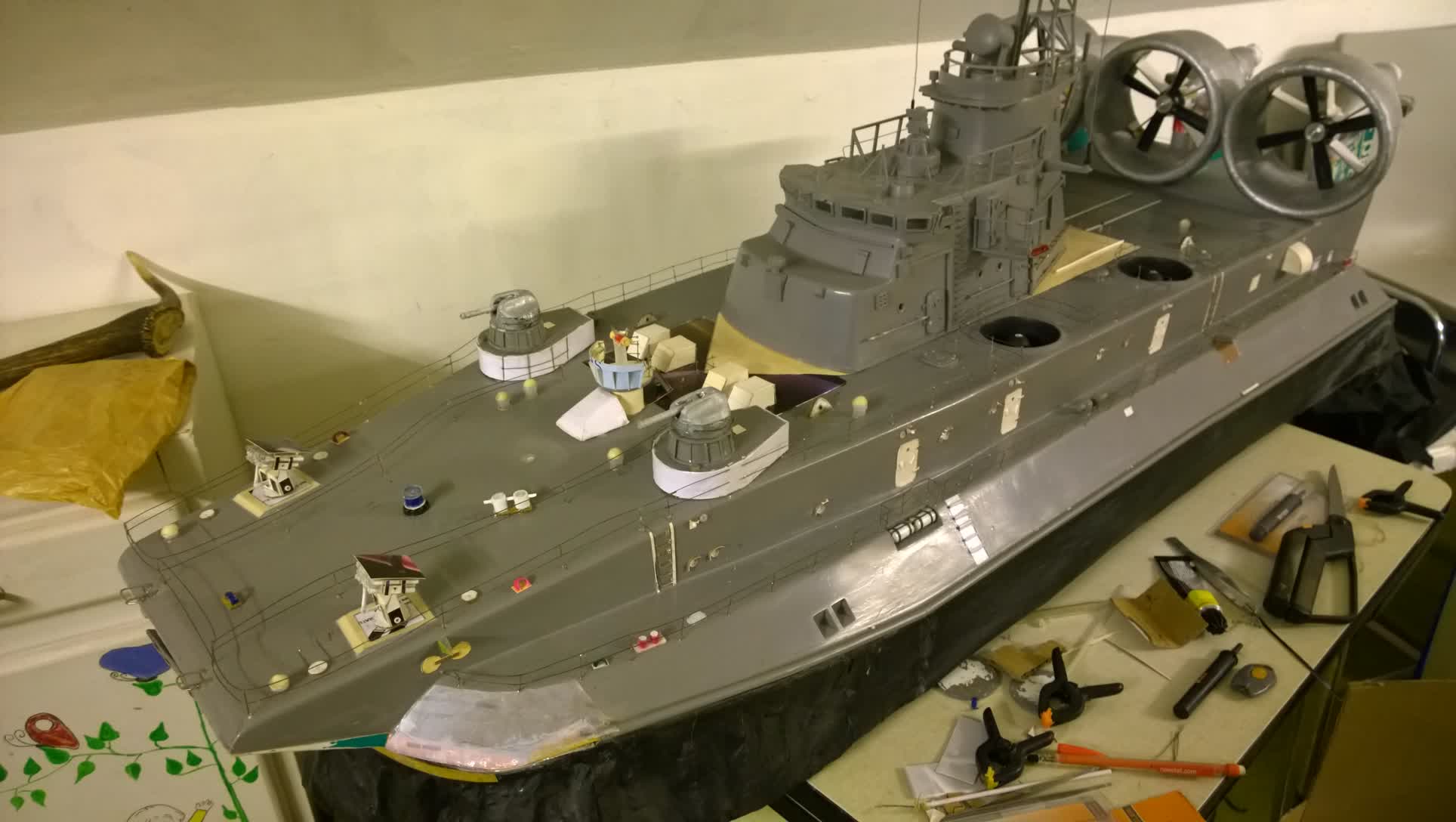
On the top, there is a plethora of details and unfortunately some faults.
If we play the game of the 7 differences between the two images, we especially notice the rocket launch tubes, the shooting station, and the central island.
My friend used the two AK 630 machine guns to hold the front inspection hatch.
In reality, these two units are on the side of the hovercraft and smaller.
I'm going to start there.
By removing the bases, the cover breaks.
I will redo it in cardboard on stiffeners.
I reduce the height of the bases, and the height of the turret supports, taking inspiration from what already exists.
For turrets and multi-tube guns, I will remake them in hard foam that I will sand to get a proper finish.
Multitube cannons are made from control cable sheaths.
In the middle, the outdoor shooting station, with its sight, will reuse elements taken from the AK 630, like the ladder, and will be completed with cardboard elements.
Thanks to a report recently found on the net, I obtained more accurate documents on these retractable units.
They would retract during navigation and come out during use.
I find that they "dress" the front well, so I decide to do more than just platforms on the deck.
First problem: I can't find a plastic tube with the right diameter.
The rocket launch tubes will be made entirely of paper.
Using a mandrel, I rolled each tube and coated it with varnish glue.
Once assembled into a battery, I made the supports and the cover.
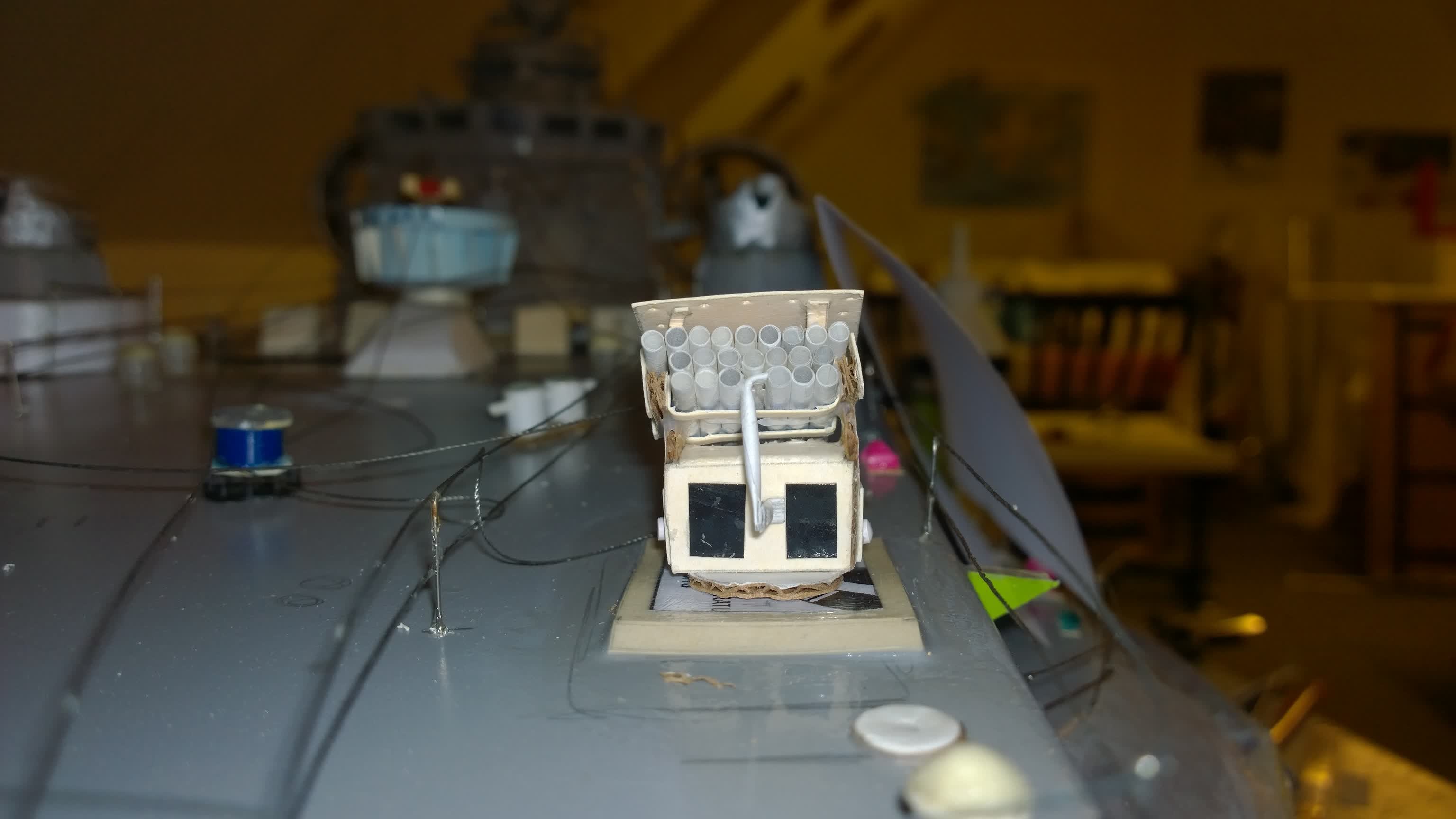
Detailed view of the left rocket launcher (not painted yet)
While it dries, I do the details of the deck.
The vents are made of pieces of tubing topped with a sculpted foam cover.
Fairleads and other mooring bittes are made of plastic.
The base of the capstan will use a piece of plug from a tube of glue.
The rest will be assembled with different pieces of recovered plastic.
Last modification: by taking profile pictures of my little Zubr and comparing them with the real one, I became aware of an anomaly in the position of the island. It is too far back.
I will redo all the electronics and make a cardboard base for the island by lengthening the back to hide the openings. This rebalances the silhouette and the weight of the machine.
We will have to rebalance everything, but it will be after the paintwork.
THE END OF THE STORY
The Zubr is now complete.
It received all the necessary equipment, but we can guess the various boxes that I used to make them.
To paint it, I disassembled the propellers and closed the holes in the lift shafts, then I surrounded the whole skirt with paper.
I used a car paint that my friend had used before: from the MOTIP brand, this paint provides color stability.
Just order the same number to be guaranteed to get the same shade.

Before painting - side view
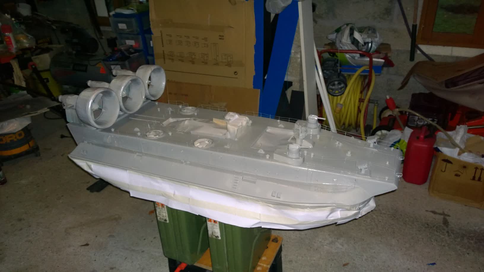
Painting (skirt protected)
The front hatch and the island will be painted separately. The cylinders, which represent the survival channels, will be painted white.
I'm also going to need black and red. For this, I will buy touch-up pens for car paint.

Side view - skirt not inflated
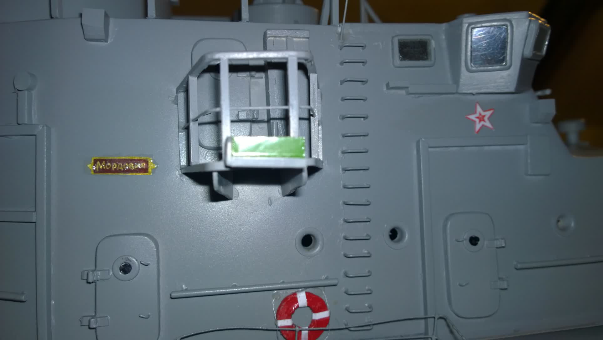
Detailed view of the island
I'm going to add small details. The lifebuoys are made of coated cardboard. There are four that will be fixed with Soliq. The stars and the Russian Navy flag come from images found on the internet. I printed them to scale before gluing them. I painted black all the interior of the portholes, the ladders' edges, guns, and hardware details.
We can see that the island is further forward, making the silhouette more balanced.
The numbers are printed on clear plastic. Only the silhouette is printed in black.
White is painted on the back, which is then glued.
On this view of the deck, we see Didier's work with this superb finish I cannot reproduce.
He used plastic card and balsa. The guardrails are also made of the same material, glued with superglue.
The scales are mid staples sunk into the balsa.
I added the star, the plate with name, and buoy.
Finally comes the time for testing:
On a good weather day without wind, we went to a small pond, with the Mordovia in its box, placed on a support to prevent the skirt from being folded.
Above the bow, there is a shelf for the radio control and accessories.
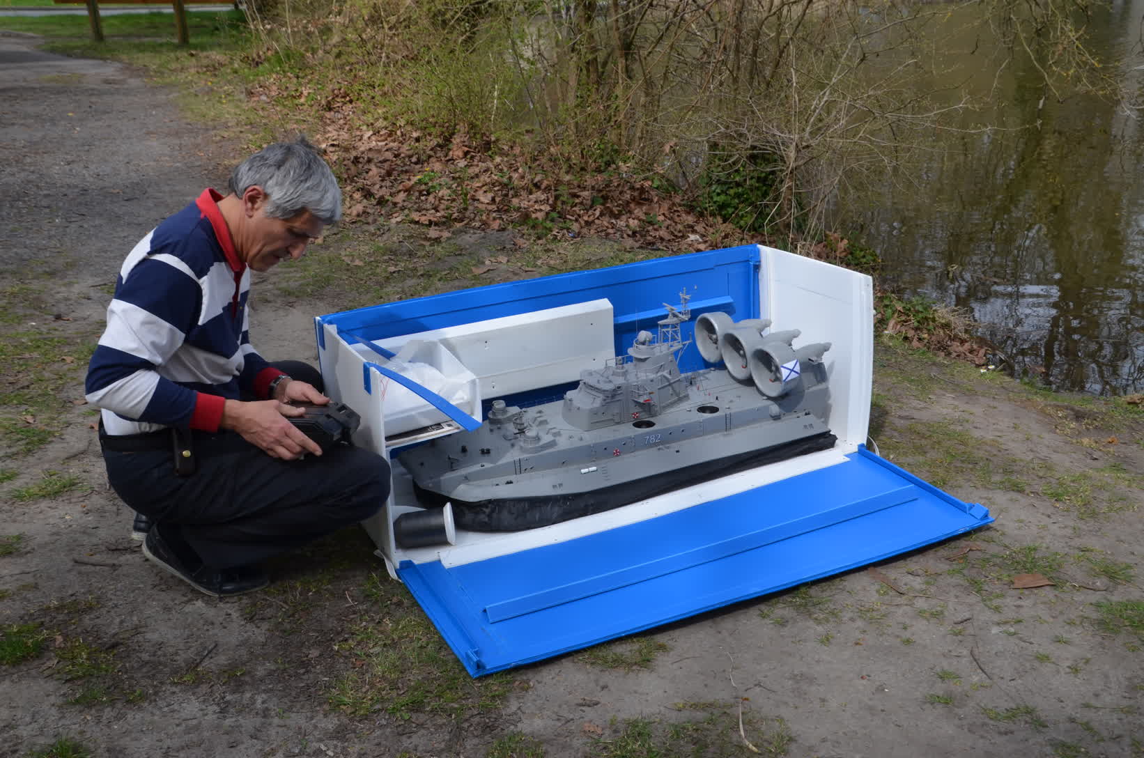
For transport, the model is held in place by large packaging bubbles. I had not thought about transport when making the calculations...
The box barely fits into my car!
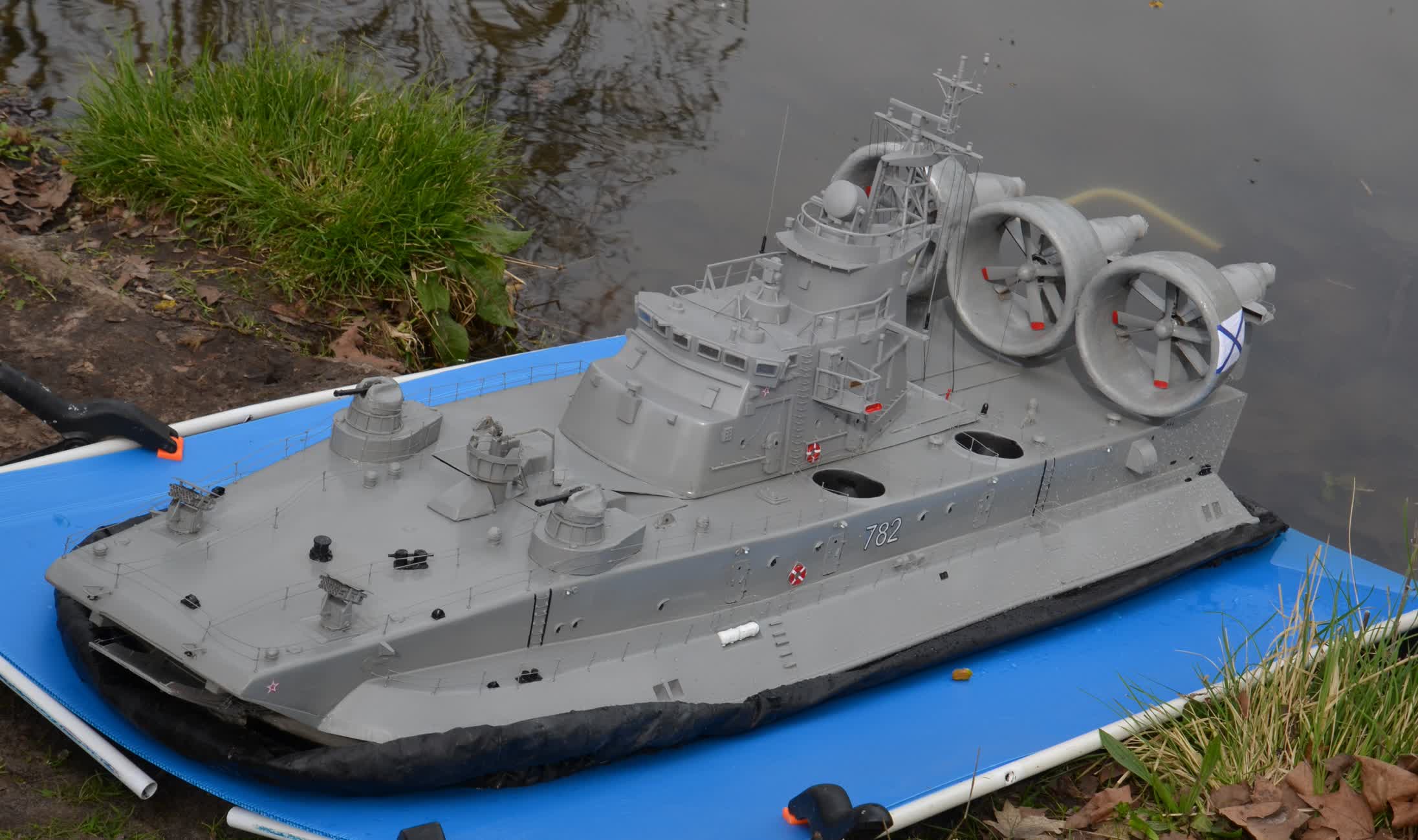
Ready to go !
After this first test, the battery was moved toward the rear to give Mordovia better balance.
The very old radio controller was replaced with a new one to avoid interference (you can see in the videos the rear door opening and closing on its own and the uneven skirt inflation).
To wrap up this 10-year journey, I'll say that I've learned a great deal.
For the next model, I'll try to include what I didn't manage to do on the Zubr: lights or radar animations to make it even more realistic.
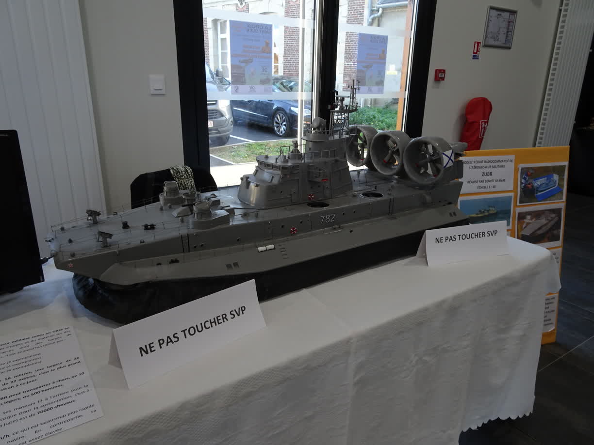
Model exhibition in France - October 2019