
Radio-controlled Gus class hovercraft
The final chapter in this saga is the Qoum 8.4, featured in the video. Its skirt is made from paraglider fabric, and the hull was crafted using bathroom insulation foam.
The main improvement over previous Qoum models lies in the fully rounded skirt design at both the front and rear — a feature that required more advanced calculations. The lift motor, a modified hairdryer turbine, is mounted at the front. All electronic components are housed in a waterproof compartment at the center of the hull.
The result is a highly responsive machine, with minimal friction, rapid acceleration, and an impressive top speed. This model still runs on a relatively heavy NiMH battery, which could be swapped for a lighter LiPo pack to boost performance even further.
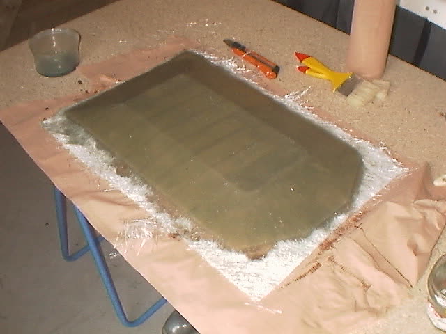
Shell and mold
A layer of fiberglass mat was laid over waxed packing tape covering the wooden form.
THE LIFT SYSTEM
For the internal structure, I use carlene sheets. I found them at a supplier that provides materials for businesses—it's the same material used to make things like construction permit signs. The sheets are sold in 120 x 80 cm formats. I work with a utility knife, an electric file, a soldering iron, and hot glue.
For the Qoum 8, I started by cutting the first two internal bulkheads and hot-glued them into place on the hull.
I then moved on to preparing the lift system. It might look simple, but there are a few rules to follow. You start by calculating the outlet area S of your lift turbine. Then you divide this into S1 = 2/3 × S and S2 = 1/3 × S. You draw S1 along the centerline, 80 mm from the rear edge of the hull, and S2 at 20 mm from the rear edge. The following picture (a bit blurry, but still understandable) illustrates this setup.
Next, you cut the holes. Above them sits the air distributor. Refer to the diagram below for clarity. One-way valves are not strictly necessary since there's only one turbine involved.
The air distributor serves two purposes: to direct airflow into both the skirt and the cushion (the central zone beneath the craft), and to support the turbine itself. I used a plastic container, which I drilled to match the turbine's diameter and positioned so it fully covered the two air outlets. I then cut off the turbine's rear section flush with the motor and kept the upper part of the fairing.
At this stage, some fitting work is needed to ensure all elements align properly. Don't forget the deflector beneath the turbine, which diverts air toward the rear skirt outlet. This deflector is a 45° inclined bulkhead that channels about one-third of the lift turbine's airflow to the back. For added strength, I also glued a reinforcement tab on each side of the turbine.
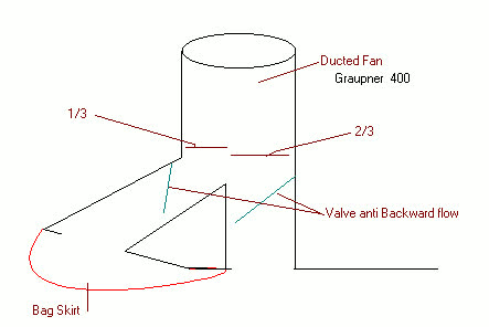
Diagram of a lift well (EDF motor assembly not shown)
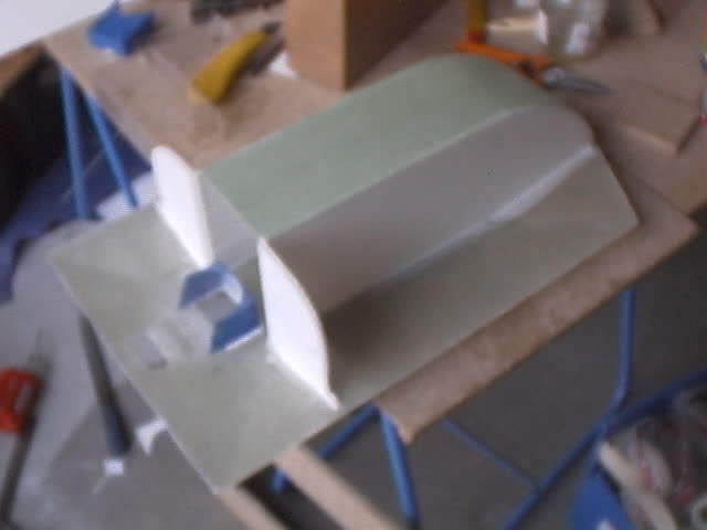
Air repartition system : we see the rear hole which feeds the skirt (sides of the hovercraft) and the front hole 2 times larger to feed the cushion (center of the hovercraft)
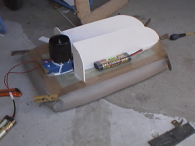
EDF all set up, air repartition system is closed, skirt briefly fixed. The batteries will help for the lifting tests.
FIRST TESTS WITH THE SKIRT – Once everything is adjusted and glued, it's time to install the skirt for testing. I grab my trusty packing tape (I'm a big fan of it), do a temporary assembly, and add some batteries to simulate the final weight.
First tears of joy: it lifts its 2.5 kg as expected. Time to move forward. Gluing the skirt requires some precision (a little) and a lot of fine adjustments. Start by drawing a line on the bottom of the hull: 7.5 cm from the rear and side edges, and 10.5 cm for the front. The gluing begins with the upper edge of the skirt, fixed to the top of the hull. This ensures better tensioning. Once dry, go back and glue the rear section along the line, then the front.
This order matters because the air entering the skirt must be able to return into the cushion through passages I leave open near the front-right and front-left panels and the start of the side sections. You make a mark on each side line: 10.5 cm from the front, 7.5 cm from the rear edge, and glue the side edges there.
If the skirt slaps too much during testing (we'll come back to that), you'll need to add holes near the inner mountings. Don't forget one or two holes at the rear's ground contact point to let out any water that might get inside—and be sure to glue on a small flap to avoid scooping water while moving forward.
After multiple failed glue attempts, I now add a few screws to secure the lower mounting.
PROPULSION – Now you've got a hovering platform that will drift on its own depending on wind and slope. You need to steer it. Two solutions here: the simplest involves two turbines with forward/reverse control directly via motor rotation. Install them and you're done. The more complex one involves reversing airflow—this is where “reversers” come into play.
I didn't have a fixed idea to begin with, so I developed things as I built. The goal: to steer right/left and reverse, using just one servo per turbine by acting only on the airflow. After much thought and many sketches, I landed on a 180° range of motion. The standard travel—45° right, 45° left—handles basic steering. Then, at the end of travel on either side, by closing the nozzle, you activate reverse thrust.
The trick is to install shutters that can completely block the turbines and direct the air out through side exits. That's it—nothing more needed.
I cut the turbines flush with the motor, keeping the rear part. Be very careful here—they're fragile, and the slightest crack tends to spread. I cut out the necessary slots in my internal bulkheads to fit the turbines, reinforcing everything by doubling up the front bulkhead. I had some transparent polypropylene—it worked well. If I had to do it over, I'd make a mold and cast the reversers in resin, because gluing polypropylene to resin (the turbine material) was difficult. I finally solved that with white bathroom-grade Rubson sealant.
Using a transparent sheet and plastic cardboard, I made the fixed shutter system that channels the redirected airflow. In the photos, you can see the rear engine cone is gone, the rear of the turbine is trimmed on the outer side, and the shutter holes are cut. The lower mounting uses a plastic cardboard bulkhead, just like those found beneath the fixed flaps of the reverser system.
Then came the second round of tests. I placed the batteries and receiver loosely and powered everything on. The craft lifts off nicely. Testing the propulsion: good thrust, since it climbs a 10° slope. On the shutter axles, I stuck packing tape to seal the turbine outlets—good reverse thrust: Qoum 8 backs up without issue. Second tears of joy.
CONTROL SURFACES – Now, how to control those shutters? First problem: servos only move 90°, but I need 180°. Second problem: the servos that come with the transmitter are too large for the available space.
I sketched out several options to solve this. Some were ineffective, others too complex for my means, others too fragile.
Then came the breakthrough moment. At the World Cup, I met the editor-in-chief of Fly International, who I had the pleasure of giving a ride on my personal hovercraft. He gave me excellent advice on servos. At Graupner, the Micro-power C261 model had both the right size and enough power for my needs. I bought them on the spot.
That left the delicate issue of extending the servo travel. I considered using gears, but that would've required mounting the servos beneath the turbines—hard to access once Qoum 8 had its body.
While researching compatible gear systems, I discovered a transmission kit for cars using toothed pulleys and belts. That changed everything. I glued a toothed pulley to the vertical axles running through the turbines, then fixed a circular damper that could seal the turbine outlet. I calculated the servo arm length and assembled everything. The belt also helps absorb vibrations. One important precaution: you must add a flange around the belt on the pulley to prevent it from slipping off on impact. I made mine from transparent polypropylene (like the turbine walls), pinched slightly around the servo to also act as a belt tensioner.

Side view of the left propulsion turbine. We can see the reverse system on the transparent part.

Glued to the air repartitor, a plate where the servos are glued. Transmission to the flaps is made with a toothed belt.

The left EDF, view from above.
TESTING
New tests: it works... well, sort of. Even the slightest pressure on the control surfaces causes the prototype to reverse. Mandatory halt. The challenge now: how to extend the control surfaces while keeping the turbine hatches operational? I stick a piece of plastic bag to the lid. New tests: too short — doesn't work. Too long — doesn't work either... And finally, it works! Third tears of joy.
With a fully charged battery, I head to the terrace. Off it goes! Over 15 minutes of operation without major issues — just a minor battery positioning tweak. It seems the number of holes under the skirt is just right; airflow is good. One minor flaw though: without propulsion, the craft slowly drifts backward.
I hand over the transmitter to my son. Unaware of the control quirks, he plays enthusiastically and shifts the control surfaces. We stop everything, adjust, and resume — same issue! In fact, the servo arms are too long. I fix it by reducing the stick range on the transmitter. With more experience, I realize the flap only needs to rotate 160°–170°, not a full 180°. Something to remember for future models — but this prototype performs well.
DRESSING
Using another white polypropylene sheet, I begin dressing Qoum 8. The sides and propulsion turbine intakes are made from raw corrugated plastic. The edges are not horizontal but slightly slanted for aesthetic effect. The rear sections are covered first, then the top, with the junction placed at the lift turbine. Decorative strips hide the seams. The design remains simple — just blue adhesive netting.
WATER TESTS
Then comes the big day. The weather is perfect, a friend is on hand with a digital camera to capture the moment, and the pond is calm.
First few meters, first problem: poor fore-aft balance. Back to the bank, move the battery, try again — twice. It finally works. I push the joysticks fully: decent steering, some speed, but disappointment — it can't rise from the water. Back to the bank again: the skirt is flooded. I forgot the anti-scooping flaps (small pieces of skirt material to seal the drainage holes at the rear). I jury-rig something and relaunch. Same issue, but I continue as long as the battery lasts. Suddenly, Qoum 8 starts listing. Back to shore. I check under the skirt — the glue has failed. I should have used screws before testing!
Back at the bench: I peel and re-glue the skirt using neoprene adhesive and reinforce it with screws through small plastic struts.
A few days later, another try — this time with a stronger battery: 8.2 V, 3300 mAh. On water, Qoum 8 picks up speed, starts to climb its bow wave... but can't overcome it. On land: 5–7 km/h. On water: half that — disappointing. Back to testing: I grab a small scale, clip it in front, and measure full-throttle thrust. Front: 125 g for 1.450 kg. Rear: 100 g. Not enough thrust for too much weight. Compared to other builds, I either need to double the thrust — or halve the weight!
CONCLUSION
I deem it suitable for indoor use — and able to cross puddles once in motion — but not capable of lifting free of water. Time to rethink the prototype: make it simpler, eliminate the reverse flaps, and reduce weight — especially by reworking the lift system. But that… will be for next time.


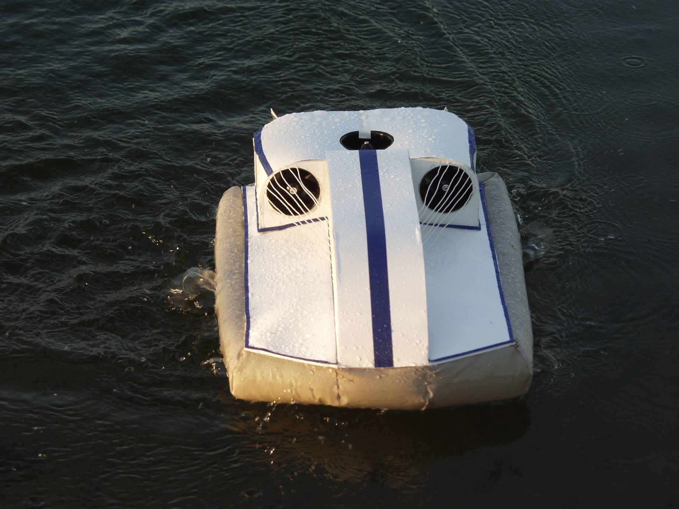
Front view. A carlene white case and adhesive were used for better aesthetics.
INTRODUCTION
Qoum 8 performs well — except on water, where its top speed of 3 to 4 km/h makes it rather unexciting. On land, however, it's a different story: good speed, excellent motor control with reversers, and precise steering. I had envisioned a versatile machine, but the outcome is clear — Qoum 8 doesn't fully deliver on that goal. A logical next step would be to create a hovercraft just as comfortable on water, without straying too far from the original specifications.
I'll keep the 500 mm hull and the three-turbine setup, but I want to simplify the machine significantly to bring the total weight under 1000 g — a sharp reduction from Qoum 8's current 1400 g with batteries. Some weights are non-negotiable: three motors (80 g × 3), three turbines (50 g × 3), receiver and ESCs: 50 g, battery: 340 g. That's already 780 g — leaving just 220 g for the skirt, the shell, and the body.
A hovercraft is essentially a volume of air surrounded by partitions. Simplification will target everything that isn't strictly necessary. Rigidity, for instance, is less critical on water than on land. Since this new version will mostly operate on water, I can eliminate the side walls of the shell, keeping only the structural elements needed to hold the skirt. For buoyancy, I've found large air pockets to wedge around the internal components.
The skirt also needs a serious weight-loss program. The current fabric is a bit too heavy — I'll need to choose a lighter material. The skirt calculations are already done; the patterns are ready. I just need to revisit the center of gravity and mass distribution to minimize electrical wiring — which will also reduce weight. The lift airflow system will be simplified as well: instead of a vertical turbine, I'll now position it at a 45° angle.
One final point: I want this model to be something a beginner can build without overcomplicating things. That means keeping the design intuitive. I've decided to split the craft into two main parts: a “two-in-one” base that combines the skirt and lower shell, and an upper module that holds the motors. The advantage is clear: in case of trouble, I can fix one section without needing to tear into the other.
These are the broad strokes of the project. The details will emerge through the build process.

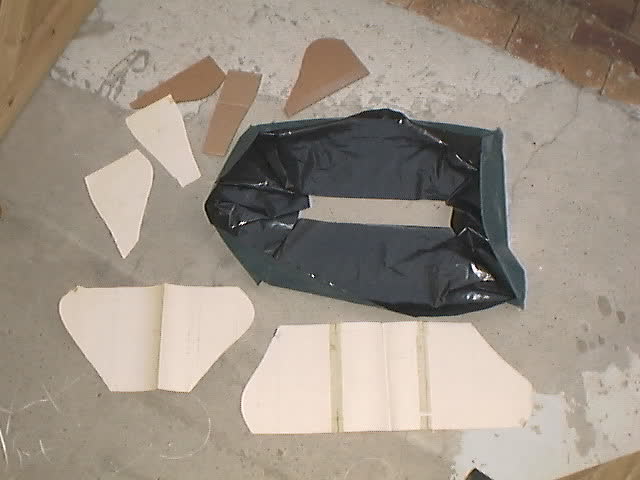
THE SKIRT
The K-Way fabric turned out to be too heavy, so I switched to plastic bags. I ran several tests, and the most promising result came from a 100-liter trash bag.
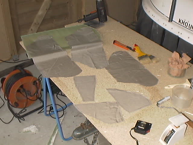
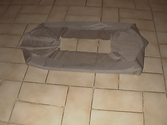
The assembly process is straightforward. I already had the patterns, so I cut each piece with an extra centimeter at both ends to overlap and join with the adjacent piece. The pieces are welded together using a soldering iron fitted with a plastic-cutting tip. I place one of the cardboard welding guides over the two pre-positioned pieces, then cut along the shape — which simultaneously trims the excess and welds the pieces together.
Cutting and welding took about an hour and a half.
In the photo: the cutting patterns, the cardboard welding guides, and the trash bag material used for the skirt.
SHELL
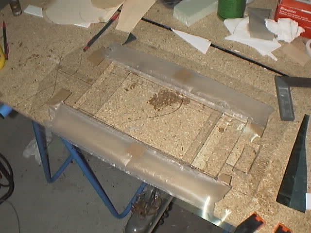
The underside won't be used, nor will the side walls. I removed them. From a polypropylene plate, I cut the top section — the only part needed to attach the skirt — measuring 500 mm in length and 300 mm in width. The lower attachment is formed directly from cuts in this upper plate. Starting 80 mm from the rear and the sides, I drew a 320 mm long rectangle. Then, marking 25 mm for each side, I hot-bent the angles where the lower sides of the skirt will be attached.
For the front and rear lower attachments, I welded reinforcements shaped like small plates. I also cut out a section for the air intake. This opening was folded with heat, both to slow down the airflow coming from the turbine and to support the weight of the lift motor just above. I added two small tabs at the front of the intake to further hold the motor, and three horizontal brackets to hold the battery in place while maintaining a gap beneath. Finally, one last bracket was added under the nose of the hull to stiffen the structure.
MOUNTING
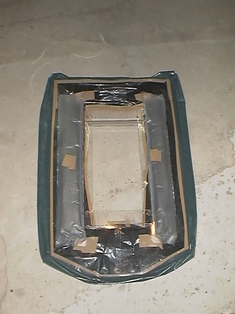
Now comes the moment for the famous packing tape. I started by attaching the two air bubbles. Their shape is ideal, and with a 30 mm diameter, they'll serve as both buoyancy aids and stiffeners. Three strips of tape per bubble, and on to the next step.
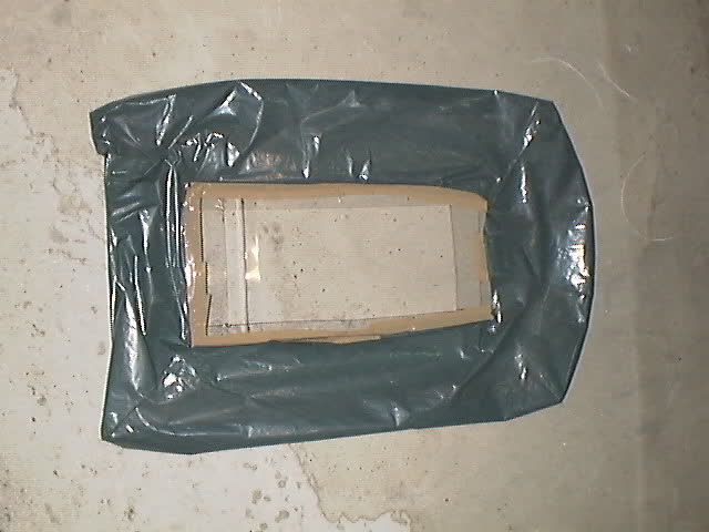
Gluing the skirt starts from the top, again using packing tape (I tested it — everything holds up to water). The original roll is too wide (50 mm), so I sliced it in half to get narrower strips that are easier to handle. The order of operations: the nose, then the front sides, followed by the long sides, and finally the rear. The tape is applied to the hull, and the skirt is adjusted right up to the edge.
Next, the bottom edge of the skirt is taped down, starting from the rear. A little trick: since this part takes a lot of air pressure, the two rear corners (green and black) get special reinforcement. Then come the front corners. The lower part of the front sides is left unglued.
Verdict from the scale: 125 grams. I'm within the weight target. Now I can move on to the next part — the motor mount.
MOTORS
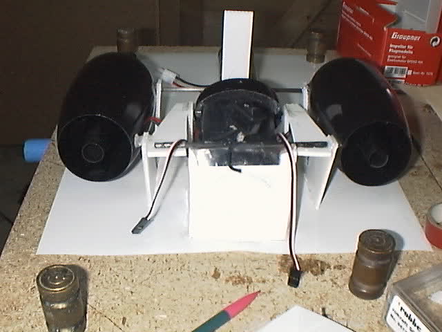
Second part of the machine: everything mechanical and control-related. A layer of double-sided tape on the shell-skirt assembly will allow me to stick a white polypropylene plate on top. On this board, I will install the three turbines and the control electronics. In front of me: three Graupner 1380 ducted fans, two Speed 400 6V motors, one Speed 400 7.2V motor, a two-way receiver, two forward/reverse ESCs, and a switch.
LIFT
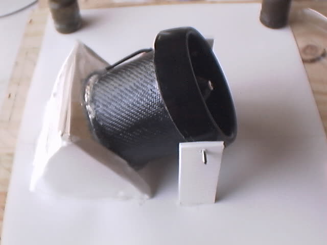
The first turbine is cut just behind the motor on the inside, and 2 cm from the front on the outside. After soldering the wires, the Speed 400 7.2V motor is installed with its propeller. Then, in the dedicated hole and its symmetrical counterpart that I drilled, I glue small threaded rods to support the front of the turbine.
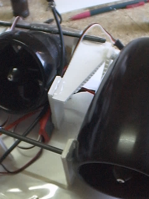
On the board, a sort of pyramid will support the rear of the turbine, which is glued in place with hot glue. The front of the turbine will rest on two “plastic cardboard” legs. The wires exit through drilled holes — the black wire goes to the back for the switch, the red wire runs forward toward the battery.
PROPULSION
I install the two Speed 400 6V motors and route their wires, which will be soldered directly in place of the ESC connectors. In the turbine mounting holes, I glue small threaded rods. Ready to go.
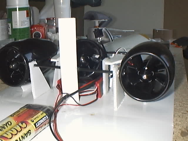
I cut four triangles from “plastic cardboard” — they will serve as lateral motor supports. I also cut three reinforcement tabs, two pieces of carbon tubing (like those used for kites), and two small tabs to place under the turbines (they'll be glued to the tray, but not to the turbines themselves).
FINAL ASSEMBLY
Everything will be glued using hot glue. Once the two side supports and the lower support have been fixed, the propulsion unit is positioned and glued onto the side. Then, I glue the front reinforcement tube — it slides over the front threaded rods. I glue the central tab (which will be trimmed flush with the tube afterward). I adjust the side tabs so that the lift motor's threaded rods and the rear threaded rod from the propulsion system can be glued into the compartments of the tongue.
Finally, I glue the second carbon tube onto the side tabs and onto the lift turbine.
Next, I solder together all the red wires, and then all the black wires, connecting them to a battery plug. The receiver, wrapped in bubble wrap, is fixed with double-sided tape to the back of the lift pyramid. Just above that, I install the lift motor's switch, so it can be accessed from the rear.
I perform a few static tests — everything seems to be working fine. The next step will be to properly assemble the two main parts, test the machine on dry land, then on water, before completing the bodywork.

FINISHING THE SUPERSTRUCTURE
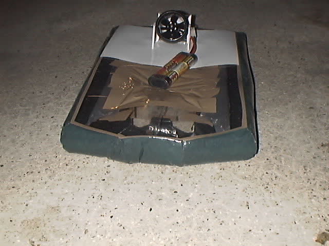
On my right, the skirt-shell; on my left, the motor assembly. The mission: assemble them and make it all work.
The first step was to do a provisional assembly and run a few tests. If the lift satisfies me, there are still some issues. The reinforcement bars are too tight and aren't positioned where they're most needed. So: disassembly and correction. The new angles are 20 × 15 mm. After checking, the white plate no longer bends under the weight of the battery, no matter its position. I'm already thinking about flight tuning: the battery's position will balance the machine — a bit more forward, or left or right, depending on trim.
Once everything looks good to me, I move on to the final assembly. I chose double-sided tape. I'll apply it in two layers: the first follows the exact contours of the skirt-shell to secure and seal; the second follows the outer edges of the motor platform to attach it firmly to the skirt-shell. Last detail: I add a handle to the front grab bar — just a simple piece of piano wire, but essential for carrying.
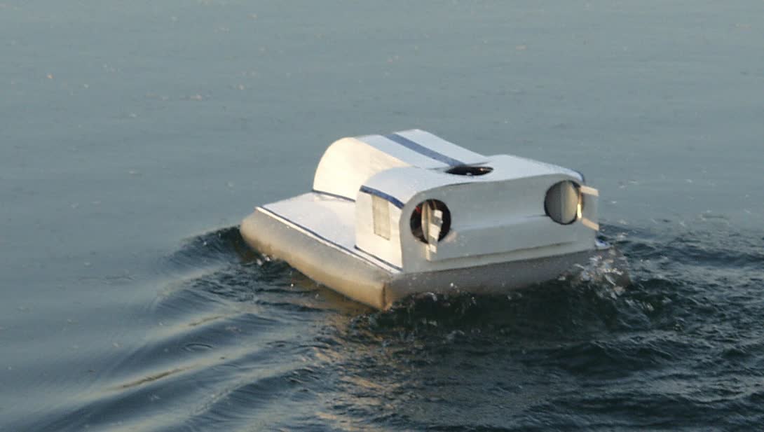
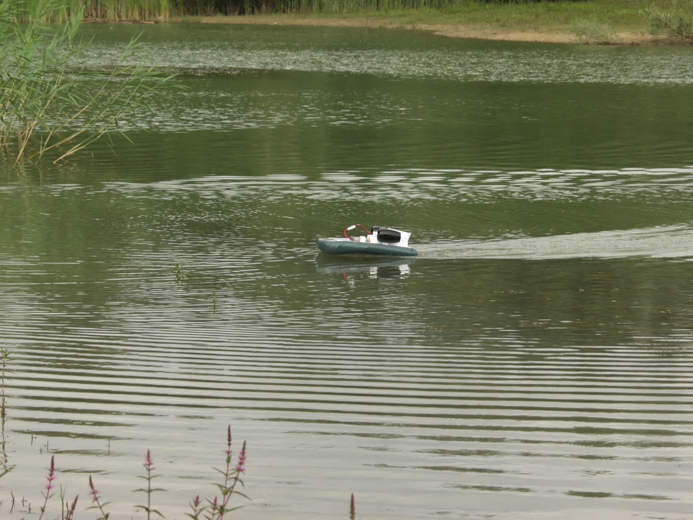
You all know the thrill of putting a machine on the water for its first test. Not far from home, on a small and quiet pond, I place Qoum 8.1. Power on: left motor OK, right motor OK, lift kicks in. Turbines howling — and off we go!
Nothing like the Qoum 8. This one works — really well, even for a first try. The rear sits a little low in the water, but it doesn't matter: it still hits 10–12 km/h. Quick return to shore, and off again for 15 minutes of fantastic gliding.
It responds well to the controls. The right motor gives a bit more than the left, so adjusting its speed fine-tunes the straight-line trajectory. It works so well that I went back home to grab another battery and invited my friend Alain. Without him, you wouldn't have had the pictures!
Almost half an hour later, I check the components: no delamination, no water in the skirt — I can return home satisfied.
Back at the workshop, I take my white polypropylene roll to make a minimal fairing over the battery. Two rails and a cover will do the job.
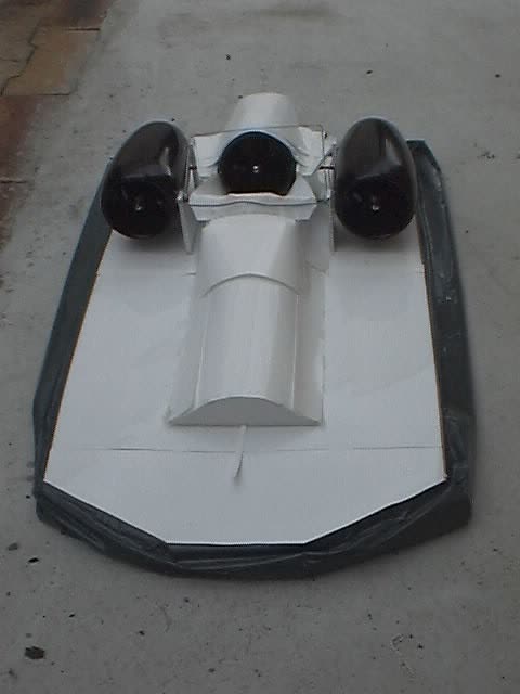
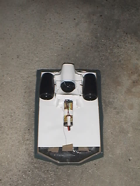
.jpg)
No more details for now — these pictures are here just to spark some new build ideas.


